Continue to Site

Welcome to EDAboard.com

Welcome to our site! EDAboard.com is an international Electronics Discussion Forum focused on EDA software, circuits, schematics, books, theory, papers, asic, pld, 8051, DSP, Network, RF, Analog Design, PCB, Service Manuals... and a whole lot more! To participate you need to register. Registration is free. Click here to register now.

[Moved] 20x4 lcd on and off problem

Status
Not open for further replies.
i have found that the signal lines(port 1) of lcd are still powered up even if i off the lcd and have also high the pins of lcd at the time when lcd is off.... and also power pins of LCD shows me 1.32v....
can anybody plzz help me.... how to make the pins to 0v
8051 has weak pull-up resistors, you need to write 0 to the ports to pull the pins to 0, involving 50 µA current per pin. For minimum sleep current, you would switch the display GND pin and VEE circuit instead of VDD and leave port 1 floating.

But presently, you are fighting with much higher power loss. If I understand right, L293D VSS and VS quiescent current is the dominant problem. It can't be disabled, you need to switch-off both supply lines. Or use a different (e.g. MOSFET) motor driver with lower idle current consumption.

Next point is voltage regulator optimization, already addressed by bigdogguru.
 

yes you r right. ...
my DC motor works on 6v-500ma...
but i think 7805 is not my problem.... because i tested my circuit in both the way.... firstly i added 7805 to the circuit to check the drain of the battery.... the batteey got drained in 10-12 hours.... but secondly i also tested the circuit without 7805.... i attached a 5v battery directly to the circuit removing 7805 out... but the problem is same.... battery gets drained again in 10-12 hours....
i think there is some mistake with my hardware or software part.... because even after i tried to low the pins through writing juat a small code(P1=0x00) of MCR..... the voltage shown on lcd signal pins and power pins are same as compared to when i high the pins of MCR using code(P1=0xff)....
do i need to add some resistance to my circuit to low the pins....
what should i do now.....

- - - Updated - - -

@FVM.... even i have tested without adding L293D to my circuit.... but the problem is same..... right now my circuit contains only 20x4 lcd.... 89S52 and keypad and IRF9540N MOSFET to control the LCD on/off... i have removed my other ics to check id they are creating the problem.... but nothing changed....

- - - Updated - - -

@FVM.... i have tried all the ways.... i wrote 0 to port 1..... 1 to port 1.... 0xff to port 1...... 0x00 to port 1..... but the situation doea not changes.... everything remains the same in all the cases....
 

Yes.... got the answer.....
it is my 89S52 Microcontroller.... who consumes the power.... i tried removing all my components from the circuit and attached onky my 89S52 to 5 v battery to check it he consumes the power or not.... but yes.... he is the one who is doing it.....
How can i stop him from doing sooo....
plz help me again....
 

Review the 89S52 datasheet about idle and power down modes. Some hardware and software prerequisitions must be fulfilled to achieve an effective power saving.
 

Have done power down mode.... 89s52 also moves to power down mode but the problem is the same....
PCON |=0x02.....
Plzzz help me
 

ground EN2, IN3 & IN4 of L293.

- - - Updated - - -

If you have got a multimeter, connect it between supply and the circuit. undo you processor, remove your motor(but leave motor driver), LCD, keypad and power the circuit. write down the current measurement value.
Then connect only the keypad, write down current measurement value & remove it again.
Now connect only the motor and write down current measurement value & remove it again.
Now connect only the processor and write down current measurement value & keep it.
Now connect LCD and write down current measurement value and remove the LCD module only.
Now connect Keypad again (processor is still there) and press a key. while holding the key write down the current measurement value.

Post your list of values here.
 

@Duresh..... Thanks a lot....
I think my problem has been resolved.....
it was L293d who was consuming my power even at ideal mode..... i removed my l293d and 7805.....and powered my circuit with 5v battery.... its working fine..... the battery does not get drained now even after 24 hours.... the voltage is completely stable at 5.14V. it drops by .01V per 3-4 minutes only after i on my lcd else it stays stable....
even if u want.. i can provide u the readings... because now my problem is.... how can i drive the motor if i rwmove L293D from the circuit....
 

Ok.
As i told above,
Try grounding EN2, IN3 & IN4 of L293
 

will it work.....????
Because anyhow i have not connected that pins to my circuit....
 

Try grounding EN2, IN3 & IN4 of L293
Will still keep an unwanted large L293 quiescent current. Review the datasheet. The part is simply not well suited for battery operation.
 

You can check how far L293 current consumption can be reduced by driving all input pins optimally. But as suggested in post #61, you should consider to cut both supply lines by transistor switches.
 

@FVM.... I have tried some other way.....
I have used 4 mosfet.... 2 IRF9540N and 2 IRF630.
1 9540 and 630 to drive motor clockwise and other set of MOSFET to drive it Anticlockwise. its working fine.... even battwry does not gets drained....
but will it sustain for long...
 

but will it sustain for long...
Any battery operated instrument design needs a calculation of battery liftetime, considering current in operation, duty cycle, idle current. I don't know what "for long" means for you.
 

i mean is this the proper way i can drive the motor clock and anticlockwise.... or will it damage my circuit in future....
 

You didn't show a schematic of your discrete MOSFET driver.

The MOSFETs should be driven with correct gate level and avoid shoottrough. If so, the solution can work well.
 

Hi friends,
Please help me as i am trying to make one motor driver through which 1.5v motor runs clock and anticlock wise....
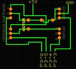
I am using lcd, keypad, 89s52 and 2 irf9540n and 2 irf630n mosfets as shown in my circuit.
I have attached the circuit diagram on mosfets.
Code:
Coonnections of mosfet gate pins.
Code:
sbit dc3=P3^3; //IRF630N
sbit dc4=P3^4; //IRF630N
sbit dc5=P3^5; //IRF9540N
sbit dc6=P3^6; //IRF9540N

At initial stage the motor will be in stop position,
Code:
dc3=0;dc5=1;
dc6=1;dc4=0;

As the button 1 is pressed from the keypad the motor runs clockwise for a specific time.
Code:
dc3=1;dc5=0;
  {
    msdelay(700);
    dc3=0;dc5=1;	
  }
Now as the button 2 is presses from the keypad the motor runs anticlockwise for a specific time.
Code:
dc6=0;dc4=1;
  {
    msdelay(700);
   dc6=1;dc4=0;
  }
But the problem is output voltage is very low. i checked with the multimeter, i am getting near about 0.85v. due to which the motor is not able to run either clock or anticlock wise. it runs but at very very low speed.
Is there any problem with my circuit and code.
Please help me.

- - - Updated - - -

P3^4 irf630n MOSFET drain pin connected to ground....
sorry not shown in circuit diagram
 

Attachments

  • untitled.JPG
    untitled.JPG
    79.7 KB · Views: 80
Last edited by a moderator:

sbit dc3=P3^3; //IRF630N
sbit dc4=P3^4; //IRF630N
sbit dc5=P3^5; //IRF9540N
sbit dc6=P3^6; //IRF9540N

P3^4 irf630n MOSFET drain pin connected to ground....
sorry not shown in circuit diagram

Neither FET is suitable for low voltage motors and a good Logic Level MOSFET should be 10% of the motor DCR.
However if this is a 1.5V motor and you only have a 5V supply, then you need to drop 1.7V in each switch but these MOSFETs looking at the Vds operating point for 4.5 to 5V Vgs cannot drive enough current.

THerefore I would suggest 2 complementary Darlingtons as Emitter Followers with suitable diode biasing to prevent shootthru. with drive levels and supply voltage used.
 

sorry its a 6v dc motor as i mentioned before....
its my mistake that i wrote 1.5v motor

- - - Updated - - -

what should i do in such cases..
i want to output to be 5v....
 

Status
Not open for further replies.

Similar threads

Part and Inventory Search

Welcome to EDABoard.com

Sponsor

Back
Top