Continue to Site

Welcome to EDAboard.com

Welcome to our site! EDAboard.com is an international Electronics Discussion Forum focused on EDA software, circuits, schematics, books, theory, papers, asic, pld, 8051, DSP, Network, RF, Analog Design, PCB, Service Manuals... and a whole lot more! To participate you need to register. Registration is free. Click here to register now.

Mosfet driver signal generator

Status
Not open for further replies.

Luis Blaugen

Newbie level 6
Newbie level 6
Joined
Mar 23, 2009
Messages
13
Helped
0
Reputation
0
Reaction score
0
Trophy points
1,281
Activity points
1,462
power mosfet driver

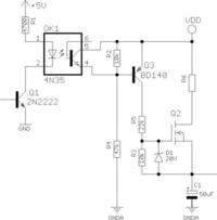
I have the following circuit: it’s a relaxation oscillator: R charges C (when mosfet is in saturation state) and when the C arrives to its maximum threshold voltage (83 v approximately), I must open the mosfet to start with the C discharge, but isolating the R, because I need to cut off this part of the circuit.
I try to open the mosfet giving a “1” to the base of 2N2222 transistor, so the opto-isolator led switch on its transistor (in fact I can’t realize this, I obtain a VSAT to high, nearly the value of the supply), closing the C-E junction of the BC639 and open the Mosfet.
All this would be the ideal that I pretend to happen, but I don’t realize my purpose, because the mosfet always conducts.
I attached the circuit sketch.

True Table: Base 2N2222 vs. Mosfet state:
base = 0 then Mosfet close (Saturation)
base = 1 then Mosfet is open

If my circuit doesn’t have a solution, why can I drive the mosfet?
Thanks and excuse me my grammar, I’m not American.
Luis Blaugen.
 

mosfet spark erosion power supply

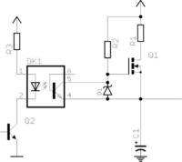
What about a circuit like this?

Added after 3 minutes:

Diode D1 can still conduct some current but I believe you can easily modify the circuit to deal with this problem.
 

555 mosfet driver

Luis Blaugen,
You don't mention the part number of the optoisolator, so I can't give a definitive answer. However, It's possible that the output transistor of the optoisolator can not supply enough current through the 2.2K resistor to bring the base voltage high enough for the 2N2222 to conduct, and turn the FET off. You might try increasing the value of the 2.2K resistor.
Regards,
Kral
 

lm555 mosfet driver

In the original circuit, the MOSFET is immediately damaged by the high negative Vgs, it can't work this way. pauloynski's suggested circuit is basically O.K. regarding charging action. But as the original circuit, it can't discharge the capacitor, it's even keeping a constant charge current through R2. It also can't charge the capacitor up to the full supply voltage.
 

lm555 timer mosfet driver

I continue with the explanation of my circuit: there are 2 electrodes connect one to the positive terminal of C and the other to GND; there is a very little space between both, and when the C charges a spark jump between the electrodes, and then the C discharges. My intention is when C discharges, halts current by the transformer of the 83V power supply, by the bridge rectifier, by the resistor and by the mosfets. Please, if you respond me, put me the components values, or better, how do you arrive to these values.
Pauloynski: can you put me the components values. When Diode D1 can still conduct some current?
FvM: I didn’t understand when and how produces the high negative Vgs.
the optoisolator is a 4N26. please, if you respond me with a sketch of a circuit, put me the components values.
thanks
 

bootstraped mosfet

Switching the transistor on put's the full capacitor voltage as Vgs.

I think, it will be very difficult to produce sparks at 80V only.
 

4n26 mosfet

Uhhhh!!! I agree with FvM. With 80V it would be very difficult obtaining a spark unless your gap has a few microns width (or less). Please let us know wath is your desired repetition rate for this circuit. In the dircuit I`ve suggested you can use the same values you posted in your circuit. The zener diode voltage should be 20V or less since it is used to prevent Vgs to go out of transistor´s specs.
 

how to remove negative pulses on lm555

thanks friends. today I will try to prepare an explanation of that I want. now, the circuit is working, but I must to make several changes to perfection it.
thanks again.
Luis
 

2n2222 for mosfet driver

I will try to explain:
My machine is an EDM (Electric Discharge Machine), it removes metal by spark erosion. If you don’t know what an EDM does, it basically uses a bunch of electrical sparks to machine away metal. You can use it to do things that are difficult, if not impossible, to do any other way. Depending on the shape of the electrode you can make square holes or use it to cut or make holes in materials that are to hard to use normal machine tools on. A good example of this would be to use it to remove a broken tap in a hole.
There are 2 electrodes: anode (cooper electrode, connect to negative of the power supply) and cathode (steel workpiece, connect to positive); besides, there is e dielectric fluid between both electrodes, which officiates such as a mean to make the spark (it allows the electrode to approach the work very closely before charges jump the gap). The gap voltage is between 70 and 90 VCC (I operate with 83 VCC).
Now, my machine is working, but I must to make several reforms, because I want it works better.
There are a transformer, a bridge rectifier, a capacitor filter and a relaxation oscillator compound by a series R-C net; the C is connected in parallel with the electrodes: when the voltage across the C arrive to the breakdown voltage of the fluid, this tension perforates itself, and a spark jump between the electrodes.
This principle is useful, for example, to drill holes in hardened steel, still in carbide or to erode cavities in a die. The electrode has a positive shape and the workpiece remains negative (bas-relief).
I put a Mosfet between R and C: it switches off the recharge circuit when sparking is going on, or when a short circuit occurs, halting flowing current from the power supply during spark discharge, which is especially important if the electrode is shorted and welded to the work. I must open the Mosfet when start the C discharge, isolating the R, transformer, bridge rectifier of the power supply and properly the Mosfet to prevent damage, and so cut off this part of the circuit that I no need when capacitor discharges, because I want just only it give me the energy that I require.
Procedure: when C is charged, the head of the machine go down, when the electrode is very near to the workpiece a series of spark jump (Mosfet open) until the threshold voltage of C arrive almost zero; it takes a few seconds, then the head go up, Mosfet closed (C begin to recharge), and continue with the process. Obviously, there is a stepper motor that moves the electrode and a stepper motor driver board, feedback with the output that controls the process.
I expect have to explain better as possible.
Sorry my grammar and thanks friends for this hand that you bring me without interest.
Luis (03-27-09)

Pauloynski: you connect the RG to the power supply; I connect it to the end of R that is in contact with the Drain. What’s the different?
 

edm ton toff

Thanks Luis. I know how it works. I´ve connected the gate resistor directly to Vcc because the MOSFET needs a Vgs voltage of about 3 to 5 volts to conduct. If you connect this resistor to the drain, the MOSFET will hardly go into saturation. If your repetition rate is low this is not a problem. Also, the circuit I´ve proposed shows a small residual current when cut off. This current flows to the output capacitor through the gate resistor and the zenner diode. This diode was placed to protect the gate because the Vgs voltage can´t rise more than 20 or 30V (please take a look at the MOSFET specs), otherwise it can be destroyed. You can increase the value of this resistor to some extent to decrease the residual current.

Added after 1 hours 53 minutes:

This circuit shows no residual current. Please size resistors according to their power dissipation. You will note that this circuit inverts the logic of the original one: when Q1 is conducting it cuts off the output current. You can deal with this by simply removing Q1 from the circuit provided you have current enough to drive the optocoupler directly. You can increase the value of R1 to 2k2 if you have trouble in driving it.

Added after 9 minutes:

One doubt: I´ve seen these kind of machines working with much larger capacitors at the output. Why are you using a small value? Is it an electrolytic type? If so I believe you are gonna have some trouble with its ESR.
 

2n2222 mosfet driver

Dear Pauloynski:
My machine has 5 capacitors: 47, 100, 220, 470 and 940µF, all electrolytic type, and everyone has its parallel 1MΩ ½ W Resistor; I can select one by one individually or group them together, choosing each one with a switch. This machine is also called “Lazarenko EDM”, and today is a rudimentary method of erosion: people can´t erode holes with polished surfaces by this method, but I´m trying to design a new machine with a high frequency pulse generator a.k.a. “modulator”; this generates thousands of sparks per second, and each tiny spark erodes a tiny hole in the work. This finished metal surface is a lot smoother than the earlier design I built, and erosion proceeds at a more regular pace. There are 2 versions of this: a machine that runs with very little values of capacitance, and other, more pretentious, where the oscillator is created with a LM555 driving a power switch-transistor. There is no info in the net, neither books, which explain this, so I work more than I hope with the proof-error method. Take me 4 years make my machine, because I live in Argentina, an agro-breeder country, not industrial like yours, is difficult and expensive purchase components and the mechanical parts (the head or clutch), and inclusive there are integrate circuits that not come into the country.
Evr’y thing you think interesant to me, please send me.
About your last comment: What trouble with its ESR? Heat for example? I say you that my capacitors heat enough, not too much, but with the hand I touch them and I note they are hot. Is there some kind of solution, aside of substitute them by low ESR capacitors?
Thanks again.
Best regards: Luis.
Also, can I set in the place of your Q2 a parallel arrange of 2 Mosfets IRFP260 joining its S and D, and placing in its gates 10 ohms resistors, and then putting together the opposite leads of the resistors to the signal? Is good this value of resistors and the types of Mosfets?
 

Re: Power Mosfet driver

Hi Luis: low capacitance electrolytics may show an ESR in the order of a few tens of ohms, that´s why they heat. The ESR differs from brand to brand and normally increases a lot during lifetime. That´s where you can go into trouble. If you can´t get low ESR ones you can try adding some non electrolytic ones in parallel with your´s to decrease ESR (not a really good solution but may help). Almost any other type will do the job. At the high capacitance end I would like suggesting your using a few electrolytic capacitors in parallel. This will help you conducting large amounts of current through many cables instead of a single one.

Added after 37 seconds:

This seems to be a nice job. Good luck.
 

Re: Power Mosfet driver

I think, in electro erosion applications, it doesn't help to use smaller low ESR capacitors in parallel. Cause the total capacitance is discharged during the pulse, the main (electrolytic) capacitors ESR still determines the losses and achievable pulse current.

As far as I understand the technique, a high current is decisive for erosion effectivity. I read about metal evaporation at 20000 to 30000 K. Or in an energy flow view, a higher ESR means that a smaller part of the stored capacitor energy is utilized for the erosion process.

On the other hand, film capacitors in 100 up to 1000 and more uF range are available for power electronics applications. They are rather bulky and more expensive than electrolytic types. Unfortunately, it's also no guaranteed, that they can endure the pulse currents in electro erosion applications in any case, just because they achieve considerably higher currents than electrolytic types. But it would be possibly to limit the peak discharge current to safe amounts by inductors.

I don't know the state-of-the-art with industrial electro erosion systems, but I would expect film capcitors and current limiting inductors, if necessary.
 

Re: Power Mosfet driver

I agree with FvM but my concert was about increasing the lifetime of the capacitors, they don´t like heat. May be someone else could help in solving this problem.
 

Re: Power Mosfet driver

Dears friend Pauloynski and FvM: I really appreciate so much their uninterested assistance.
What about my comment about paralleling mosfets? It’s correct?
Thanks again.
 

Re: Power Mosfet driver

To quickly turn on a MOSFET you need to source a large current to the gate in order to charge its capacitance. After it is charged almost no more current is needed. The circuit you´ve proposed does it through a 4k7 resistor conneted to the drain (or the 80V supply) which will source only a fraction of the required current. This means it will not reach the lowest Rdon for a while and that is a bad condition since the MOSFET will heat and will not charge the output capacitor as fast as you need. The time to charge the output capacitor will also be dependent on the value of the series resistor connected to the drain. In order to start with any calculation you must define the repetition rate you want to recharge it. In your circuit, placing a 10Ω resistor in series with the gates makes no sense since there is a much larger resistor (4k7) in series with them. In my opinion this is not a good solution. You can try using a more powerfull MOSFET (may be with lower Vds, 150 or 120V seems to be enough if there is no inductive load) or a high side gate driver like **broken link removed** Also, as you increase the charging rate so does the heat on the output capacitors.
 

Power Mosfet driver

change the mosfet to a logic level type and drive it directly from VCC instead.
 

Power Mosfet driver

I didn't yet care about the involved MOSFET type and possible need for more current or power capacity. A parallel circuit isn't a problem. Your gate circuit is rather high impedance, so the individual gate resistors also aren't critical and can have any value between 10 and 100 ohms.

I understand that the circuit is based on using a charging resistor and operate the FET as a switch. The minimum voltage drop of Vgs,on is a serious disadvantage of all discussed circuit variants. Using logic-level MOSFET can reduce but not remove it. Unfortunately, it also limits the choice of suitable devices.

A more general solution would be one of this:
- a PMOS-FET
- a gate circuit utilizing bootstrap
- an isolated gate driver supply respectively an auxilary voltage stacked upon V+. Cause the input voltage supply is AC with a bridge rectifier, there are quite simple voltage doubling circuits available (2 diodes + 2 small capacitors).

P.S.: A switched mode buck converter with constant current output would be an optimal solution to my opinion. The charge current could be easily programmed in this case.
 

Re: Power Mosfet driver

Please find attached a few articles and diagrams on this subject. Use them as a guide in your project.
 

Re: Power Mosfet driver

Thanks for the compilation. Considering the fact, that e.g. Esp&#64cenet has more than 1500 hits for patents related to "electro erosion", it can be only an arbitrary snippet of available literature. As previously said, I don't have more than a basic understanding of the basic operation principle. Thus it's valuable at least to me. Luis as an EDM practical man has most likely his own view on the presented literature. But some of it also discusses electrical circuit details and may be interesting already by this part.
 

Status
Not open for further replies.

Similar threads

Part and Inventory Search

Welcome to EDABoard.com

Sponsor

Back
Top