Continue to Site

Welcome to EDAboard.com

Welcome to our site! EDAboard.com is an international Electronics Discussion Forum focused on EDA software, circuits, schematics, books, theory, papers, asic, pld, 8051, DSP, Network, RF, Analog Design, PCB, Service Manuals... and a whole lot more! To participate you need to register. Registration is free. Click here to register now.

mobile antenna as a rectenna

Status
Not open for further replies.
but now i have picked it and i will have to do it so please guide me in designing an antenna which can receive a minimum 1mV at a distance of minimum of 40 meters.

what power and voltage you need? What application is this?! If you will be more specific somebody can tell you solution!
 

i need atleast 1Mv at the input of the voltage doubler that is it i have made the rest of the circuit its a temperature sensor that works on 3V
 

there's no way you are going to get a few microVolts from the antenna up to 3V.
And on the wild chance that you could actually produce something close to 3V,
there is not going to be any current to actually power anything

cheers
Dave
 

.... and be careful with the units you use, 1Mv is 1,000,000V, not 0.001V !

For a voltage doubler to work you need to have at least as much input voltage as the diodes need to make them conduct. As you would be forced to use small signal microwave diodes that would be a minimum of about 400mV. As a rule of thumb, each time you double the voltage you also reduce the current available by about 60% so when you start with 1mV at a few microamps you have no chance of boosting it to 3V at say 10mA.

Brian.
 

Untitled.pngso what shall i do now?
OK i got this rectifier pic here i cannot understand how it is working its an ADS diagram can any one explain it please?please reply fast
i need to design this pifa antenna tomorrow in every way so please reply and also share the design considerations

sorry for using MV instead of mV
by the way can i use it to improve efficienciency of a solar cell i mean by moulding a PIFA on a solar cell

- - - Updated - - -

ADS layout for the braodband rectifying circuit.e.png
 
Last edited:

Now you are really confusing us! The idea of a solar cell was to replace the rectenna completely, it was an alternative power source, not one to be used with your phone antenna.

The present design is absolutely fine as long as you mount it ON the transmitting antenna but if you do that it would be far more efficient to disconnect the cell antenna and connect it straight to your rectifier. Be careful when climbing the mast and standing in front of the transmitting antenna, the radiation can be very dangerous.

Brian.
 

perhaps i havent been able to explain what i really want to do ...ok here is te abstract of my proposal
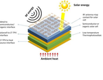
The growth of multifunction, high efficiency energy harvesters has greatly increased in the past few years. Using several energy sources available in the environment such as, solar, thermal, and RF, researchers have been able to come up with new ways to optimize harvesting efficiency and output power. The process of energy harvesting involves capturing ambient energy in the environment and converting it into power that can be stored and reused at any time. The available power being retrieved from a harvesting device is very limited, which is why studies are being done to integrate different energy harvesting techniques to optimize the output. An example layout of this kind of device is shown below

- - - Updated - - -

Untitled1.png
in the start i wanted to harvest RF energy only but as i went in to the field i ralized tht the power density of rf alone is very low and it will never be able to work .then i just hit this idea of combining both and it will make the solar cell more efficient and it will also help to chage the batteries to some extent in the night.i have desined everything.all i left is the antenna the mathing circuit and the voltage doubler
can you tell me what should be the antenna design considerations for this purpose>?
 

What application is this?!

I think this threads stinks. Total ignorance to technical concerns and application that makes no sense, and just one question: how can we get 1mV out of a nearby phone signal?

There are guys who want to trigger explosives when a mobile phone is detected.
 

I still say forget the RF idea. Your power source would be 99.999% solar and 0.001% RF. Given that a PV panel works out of the box and produced high current and the rectenna will take weeks of development you can see why we say it isn't worth the effort.

Also, as pointed out earlier, you might get one or two mV from the rectenna but it takes at least 400mV before a voltage doubler will start to work at all. When you double the voltage you don't double the power, in fact you get less. The voltage will increase but the current capability will decrease and overall you get less usable power at the output. For example, if you could harvest 1mV at say 0.5mA (= 0.0000005W) and double it to say 1.5mV (if that was actually possible) you might get 3 - 4 uW of power to charge your battery. In other terms, even if you could get enough voltage, an AA cell at 0.1C would take around 22.8 YEARS to charge up!

Think why cell phones used tuned receive antennas followed by high gain amplifiers just to make enough sound to drive an earphone. It's because the signal is incredibly tiny.

Brian.
 

I think this threads stinks. Total ignorance to technical concerns and application that makes no sense, and just one question: how can we get 1mV out of a nearby phone signal?

There are guys who want to trigger explosives when a mobile phone is detected.

you are underestimating RF energy you can easily get 1mV from a mobile signal placed at a distance of 40m from msat

- - - Updated - - -

I still say forget the RF idea. Your power source would be 99.999% solar and 0.001% RF. Given that a PV panel works out of the box and produced high current and the rectenna will take weeks of development you can see why we say it isn't worth the effort.

Also, as pointed out earlier, you might get one or two mV from the rectenna but it takes at least 400mV before a voltage doubler will start to work at all. When you double the voltage you don't double the power, in fact you get less. The voltage will increase but the current capability will decrease and overall you get less usable power at the output. For example, if you could harvest 1mV at say 0.5mA (= 0.0000005W) and double it to say 1.5mV (if that was actually possible) you might get 3 - 4 uW of power to charge your battery. In other terms, even if you could get enough voltage, an AA cell at 0.1C would take around 22.8 YEARS to charge up!

Think why cell phones used tuned receive antennas followed by high gain amplifiers just to make enough sound to drive an earphone. It's because the signal is incredibly tiny.

Brian.

i am actually talking about doing it within the premises of a msat.......
you will have more power density there dont you?
and its my final year project i will have to it in any way
the application is to run a temperature sensor placed in a msat territory

- - - Updated - - -

and brian i cannot change this project now
so please it will be better if you guide me to do it
we dont have the option to change
i have chosen PIFA
i want you and all other fellows to help me in designing it
and then the matching network and finally the rectifier
 

We are telling you it isn't practical to do it at all, no matter how you design it. It isn't that we wont help you, it's that you are asking the impossible.

You are looking for a power rectifier that can work at 900Mhz/1.8GHz and has an incredibly low Vf, nobody makes them and probably never will. As for mounting it right next to a transmitting antenna, think of this analogy: It's like powering a light bulb, and placing a PV panel next to it to harvest the electicity. The obvious efficient way to do it not to have a lightbulb or PV at all and connect directly to the light bulb supply. You are going to an enormous amount of trouble to wreck the stations output when a power source must already be present there anyway.

An aside point: have you considered whether your sensor will operate in a high field strength? Most will not.

Brian.
 
so what you purpose now?
i cannot change it
i will have to show them something?
i can make little changes but i cannot change the whole project you also understand this
 

Last edited:
ok i think we should start working now
i need to design a PIFA antenna.with 900Mhz resonant frequency

- - - Updated - - -

ok i think we should start working now because i dont have time to discuss the feasibility of this
i need to design a PIFA antenna first.with 900Mhz resonant frequency

- - - Updated - - -

atleast we should give it a try
 

Status
Not open for further replies.

Similar threads

Part and Inventory Search

Welcome to EDABoard.com

Sponsor

Back
Top