Continue to Site

Welcome to EDAboard.com

Welcome to our site! EDAboard.com is an international Electronics Discussion Forum focused on EDA software, circuits, schematics, books, theory, papers, asic, pld, 8051, DSP, Network, RF, Analog Design, PCB, Service Manuals... and a whole lot more! To participate you need to register. Registration is free. Click here to register now.

MikroC & SD CARD & PIC18F4520

Status
Not open for further replies.
Hi guys,
I plan to do coding and test with simulation instead waiting the PIC18F4520 coming stock.
I got question to ask:

From proteus ISIS 7 simulation software,
Is it possible to write a text file and read text file from the sd card image file from simulation there ?

If does, what software or necessary steps do I need to know ?

I also tested with another example code with using MMC_FAT_16 codes, it doesnt work correctly with simulation.
Result: Initialization failed.
 
Last edited:

Updated question:
I have tried out the MikroC example from folder: ExtraBoard/MMC.
My simulation Virtual Terminal get weird result with/without SD card inserted as shown below:

FAT16_hyperterminal_problems.JPG
 

I have tried out the MikroC example from folder: ExtraBoard/MMC.
My simulation Virtual Terminal get weird result with/without SD card inserted as shown below:

The MikroC MMC Library unfortunately does not support the PIC16F family.

Reference MikroC Pro User Manual, pg 368, Section MULTI MEDIA CARD LIBRARY:

Notes:
- Library works with PIC18 family only;
- The library uses the SPI module for communication. User must initialize
SPI module before using the SPI Graphic Lcd Library.
- For MCUs with two SPI modules it is possible to initialize both of them and
then switch by using the SPI_Set_Active() routine.
- Routines for file handling can be used only with FAT16 file system.
- Library functions create and read files from the root directory only;
- Library functions populate both FAT1 and FAT2 tables when writing to files,
but the file data is being read from the FAT1 table only; i.e. there is no
recovery if FAT1 table is corrupted.

It appears you will have to wait for your PIC18F replacement.

BigDog
 
  • Like
Reactions: FvM

    FvM

    Points: 2
    Helpful Answer Positive Rating
Anyone here know how to create image file for storing and writing file ?
I searched internet source, they all recommended this "dd".
This is link, chrysocome.net - dd for windows
Anyone know how to use this ?

Yesterday, I used other people mmc image file, finally the codes're working.
Right now, I want to learn how to create these quote above message I replied.
Do you know how to use it ?

---------- Post added at 15:10 ---------- Previous post was at 15:06 ----------

Concerning the Proteus' Virtual Terminal, each character will be transmitted as it is typed into the terminal.

Thanks, may I know how does "each character" transmitted ?
I didnt see any inputs from Virtual Terminal's edit properties.
 
Last edited:

Hi guys,
Hope you guys doing fine recently.

I have sucessfully test mikroC FAT16 example.
Right now, I have problem for writing simple "Hello World" in text file.

Here's the result shown below:
Code:
[COLOR="#FF0000"]Hello World  MMC init FAILED Test End MMC init OK ? H?  Hello World  MMC init FAILED Test End MMC init OK ? H?  Hello World  MMC init FAILED Test End MMC init OK ? H?  Hello World  MMC init FAILED Test End MMC init OK ? H?  Hello World  MMC init F[/COLOR]

Why it does not show "Hello World" only instead printed unnessary words in the text file ?

Here's my coding:
Code:
// MMC module connections
sbit Mmc_Chip_Select           at LATC2_bit;  // for writing to output pin always use latch (PIC18 family)
sbit Mmc_Chip_Select_Direction at TRISC2_bit;
// eof MMC module connections

// LCD 16x2 connections
// Lcd pinout settings
sbit LCD_RS at RB4_bit;
sbit LCD_EN at RB5_bit;
sbit LCD_D7 at RB3_bit;
sbit LCD_D6 at RB2_bit;
sbit LCD_D5 at RB1_bit;
sbit LCD_D4 at RB0_bit;

// Pin direction
sbit LCD_RS_Direction at TRISB4_bit;
sbit LCD_EN_Direction at TRISB5_bit;
sbit LCD_D7_Direction at TRISB3_bit;
sbit LCD_D6_Direction at TRISB2_bit;
sbit LCD_D5_Direction at TRISB1_bit;
sbit LCD_D4_Direction at TRISB0_bit;
// End of LCD 16x2 connections

const LINE_LEN = 43;
char err_txt[20]       = "FAT16 not found";
char file_contents[LINE_LEN] = "XX MMC/SD FAT16 library by Anton Rieckertn";
char           filename[14] = "MIKRO00x.TXT";          // File names
unsigned short loop, loop2;
unsigned long  i, size;
char           Buffer[512];


// Creates new file and writes some data to it
void M_Create_New_File() {
  //filename[7] = 'A';
  Mmc_Fat_Set_File_Date(2010, 4, 19, 9, 0, 0); // Set file date & time info
  Mmc_Fat_Assign(&filename, 0xA0);          // Find existing file or create a new one
  Mmc_Fat_Write("Hello World",255);
}


// Main. Uncomment the function(s) to test the desired operation(s)
void main() {

  ADCON1 |= 0x0F;                  // Configure AN pins as digital
  CMCON  |= 7; 
  TRISB = 0;                    // Turn off comparators
  PortB = 0xFF;


  Lcd_Init();
  // Initialize SPI1 module
  SPI1_Init_Advanced(_SPI_MASTER_OSC_DIV64, _SPI_DATA_SAMPLE_MIDDLE,_SPI_CLK_IDLE_LOW, _SPI_LOW_2_HIGH);

  // use fat16 quick format instead of init routine if a formatting is needed
  if (Mmc_Fat_Init() == 0) {
    Lcd_Cmd(_LCD_CLEAR);
    Lcd_Out(1,1,"MMC init OK");
    // reinitialize spi at higher speed
    SPI1_Init_Advanced(_SPI_MASTER_OSC_DIV4, _SPI_DATA_SAMPLE_MIDDLE, _SPI_CLK_IDLE_LOW, _SPI_LOW_2_HIGH);
    M_Create_New_File();
    Lcd_Out(1,1,"Test End");


  }
  else {
    Lcd_Cmd(_LCD_CLEAR);
    Lcd_Out(1,1,"MMC init FAILED"); // Note: Mmc_Fat_Init tries to initialize a card more than once.
                                   //       If card is not present, initialization may last longer (depending on clock speed)
  }

}


TAKE NOTE : I said tested with SIMULATION PROTEUS ISIS 7, not yet tested with hardware due to waiting PIC18F4520 stock to come.
 

You need to initialize the file pointer by using either Mmc_Fat_Append() or Mmc_Fat_Rewrite():

Code:
// Creates new file and writes some data to it
void M_Create_New_File() {
  //filename[7] = 'A';
  Mmc_Fat_Set_File_Date(2010, 4, 19, 9, 0, 0); // Set file date & time info
  Mmc_Fat_Assign(&filename, 0xA0);          // Find existing file or create a new one
  [COLOR="#FF0000"]Mmc_Fat_Rewrite();                             // Initialize File Pointer to Clear File[/COLOR]
 [COLOR="#FF0000"] Mmc_Fat_Write("Hello World\r\n",13);[/COLOR]
}

Also the second parameter of Mmc_Fat_Write() should be adjusted to the actual length of the string, 13, after I added an return and newline.

Let me know if this takes care of the issue.

BigDog
 
Last edited:

You need to initialize the file pointer by using either Mmc_Fat_Append() or Mmc_Fat_Rewrite():

Code:
// Creates new file and writes some data to it
void M_Create_New_File() {
  //filename[7] = 'A';
  Mmc_Fat_Set_File_Date(2010, 4, 19, 9, 0, 0); // Set file date & time info
  Mmc_Fat_Assign(&filename, 0xA0);          // Find existing file or create a new one
  [COLOR="#FF0000"]Mmc_Fat_Rewrite();                             // Initialize File Pointer to Clear File[/COLOR]
 [COLOR="#FF0000"] Mmc_Fat_Write("Hello World\r\n",13);[/COLOR]
}

Also the second parameter of Mmc_Fat_Write() should be adjusted to the actual length of the string, 13, after I added an return and newline.

Let me know if this takes care of the issue.

BigDog

Yap, it does affected. I just solved it by referring example. Thank you for pointing out.
Anyway, I wonder how do I exactly write each bytes into same text file from each input UART ?
Because in void Mmc_Fat_Write(char *fdata, unsigned data_len);
data_len need to be specified.
 

You could use a counter variable which you increment each time a character is added to a character buffer, however you would need to limit the number of received characters before writing the buffer to the MMC. This would allow you to continue using Mmc_Fat_Write(char *fdata, unsigned data_len) with the data_len being the counter.

Another alternative would be to simply write a single character at a time by inserting Mmc_Fat_Write(receivechar, 1) in the appropriate position of your UART receiving routine.

You would of course need to initialize the file pointer using the Mmc_Fat_Append() in the UART receiving routine.

BigDog
 
  • Like
Reactions: FvM

    FvM

    Points: 2
    Helpful Answer Positive Rating
You could use a counter variable which you increment each time a character is added to a character buffer, however you would need to limit the number of received characters before writing the buffer to the MMC. This would allow you to continue using Mmc_Fat_Write(char *fdata, unsigned data_len) with the data_len being the counter.

Another alternative would be to simply write a single character at a time by inserting Mmc_Fat_Write(receivechar, 1) in the appropriate position of your UART receiving routine.

You would of course need to initialize the file pointer using the Mmc_Fat_Append() in the UART receiving routine.

BigDog

I prefer "9 characters" UART/RS232 each input, meaning writing every 9 characters, then next "9 characters" input will be written in the next line.
Example : Inside text file:

123456789
987654321
123456789
987654321

when I sent input of

123456789
987654321
123456789
987654321
 

Ok,

Set the buffer length to nine as well as the data_len argument of Mmc_Fat_Write(receivechar, 9).

BigDog

Bad news, it doesnt even write correct characters into my text file.
Weird characters were written.


Here's my coding.

Code:
// Define necessary definitions
char           filename[14] = "MIKRO00x.TXT";          // File names
unsigned char uart_rd;
unsigned char data;
unsigned char temp[10];
unsigned char number =0;

// MMC module connections
sbit Mmc_Chip_Select           at LATC2_bit;  // for writing to output pin always use latch (PIC18 family)
sbit Mmc_Chip_Select_Direction at TRISC2_bit;
// eof MMC module connections

// LCD 16x2 connections
// Lcd pinout settings
sbit LCD_RS at RB4_bit;
sbit LCD_EN at RB5_bit;
sbit LCD_D7 at RB3_bit;
sbit LCD_D6 at RB2_bit;
sbit LCD_D5 at RB1_bit;
sbit LCD_D4 at RB0_bit;

// Pin direction
sbit LCD_RS_Direction at TRISB4_bit;
sbit LCD_EN_Direction at TRISB5_bit;
sbit LCD_D7_Direction at TRISB3_bit;
sbit LCD_D6_Direction at TRISB2_bit;
sbit LCD_D5_Direction at TRISB1_bit;
sbit LCD_D4_Direction at TRISB0_bit;
// End of LCD 16x2 connections


// Creates new file and writes some data to it
/*void M_Create_New_File() {
  //filename[7] = 'A';
  Mmc_Fat_Set_File_Date(2010, 4, 19, 9, 0, 0); // Set file date & time info
  Mmc_Fat_Assign(&filename, 0xA0);          // Find existing file or create a new one
  Mmc_Fat_Rewrite;
  Mmc_Fat_Write("Hello World",12);
} */


// Main. Uncomment the function(s) to test the desired operation(s)
void main() {

  ADCON1 |= 0x0F;                  // Configure AN pins as digital
  CMCON  |= 7; 
  TRISB = 0;                    // Turn off comparators
  PortB = 0xFF;

  UART1_Init(19200);
  Delay_ms(100);
  Lcd_Init();
  // Initialize SPI1 module
  SPI1_Init_Advanced(_SPI_MASTER_OSC_DIV64, _SPI_DATA_SAMPLE_MIDDLE,_SPI_CLK_IDLE_LOW, _SPI_LOW_2_HIGH);

  // use fat16 quick format instead of init routine if a formatting is needed
  if (Mmc_Fat_Init() == 0) {
    Lcd_Cmd(_LCD_CLEAR);
    Lcd_Out(1,1,"MMC init OK");
    // reinitialize spi at higher speed
    SPI1_Init_Advanced(_SPI_MASTER_OSC_DIV4, _SPI_DATA_SAMPLE_MIDDLE, _SPI_CLK_IDLE_LOW, _SPI_LOW_2_HIGH);
   do {
   if (UART1_Data_Ready()){              //<------ Check if a character has been received before reading
       uart_rd = UART1_Read();     // read the received data,
       UART1_Write(uart_rd);

       temp[number] = uart_rd;
       number = number +1;
       if (number == 9) // temp storing  string
       {
          Lcd_Cmd(_LCD_CLEAR);
          Lcd_cmd(_LCD_RETURN_HOME);
          Lcd_out(1,1,temp);
          Mmc_Fat_Set_File_Date(2010, 4, 19, 9, 0, 0); // Set file date & time info
          Mmc_Fat_Assign(&filename, 0xA0);          // Find existing file or create a new one
          Mmc_Fat_Rewrite;
          Mmc_Fat_Write(temp,9);
          Lcd_Cmd(_LCD_CLEAR);
          Lcd_Out(1,1,"Test End");
          number =0;
        }

       }
    } while(1);


  }
  else {
    Lcd_Cmd(_LCD_CLEAR);
    Lcd_Out(1,1,"MMC init FAILED"); // Note: Mmc_Fat_Init tries to initialize a card more than once.
                                   //       If card is not present, initialization may last longer (depending on clock speed)
  }

}
 
Last edited:

Anyone here can suggest solution or idea how to solve it ?
I'm still stuck on it.
Well, back to basic FAT16 writing, how'd I write new line data in text file for each input ?
I did search around, they mentioned about "ASCII" for new line and tab.
However I have tried with following:
Mmc_Fat_Write("%12",2) // %12 for new line
Mmc_Fat_write("%12",3) // %12 for new line

It does not work at all.
 

Hmm, no people can suggest idea to solve it ?

Have you successfully establish RS-232 communications with the virtual terminal in Proteus?

You also have changed the BAUD rate from 9600 to 19200. I highly recommend you make small single incremental changes, rather than several changes all at once.

Otherwise, it is difficult for you to troubleshoot the exact cause of the issue. Is it the RS-232, MMC or LCD sections creating the issue?

Once you have successfully establish RS-232 communications with the virtual terminal in Proteus at 9600 BAUD, post your RS-232 code.

Well, back to basic FAT16 writing, how'd I write new line data in text file for each input ?
I did search around, they mentioned about "ASCII" for new line and tab.
However I have tried with following:
Mmc_Fat_Write("%12",2) // %12 for new line
Mmc_Fat_write("%12",3) // %12 for new line

As the code changes I provided in post #127 demonstrate, you must write both a "return" and a "newline."

Code:
// Creates new file and writes some data to it
void M_Create_New_File() {
  //filename[7] = 'A';
  Mmc_Fat_Set_File_Date(2010, 4, 19, 9, 0, 0); // Set file date & time info
  Mmc_Fat_Assign(&filename, 0xA0);          // Find existing file or create a new one
  Mmc_Fat_Rewrite();                             // Initialize File Pointer to Clear File
  Mmc_Fat_Write("Hello World[COLOR="#FF0000"]\r\n[/COLOR]",13);
}

For future reference, if you are going to use a counter, such as "number" to track the number of characters received and to be written to the card media, use it throughout your code, rather than hardcoding specific values. Using this principle routinely can prevent coding errors when future changes are made.

Code:
temp[number] = uart_rd;
       number = number +1;
       if (number == 9) // temp storing  string
       {
          Lcd_Cmd(_LCD_CLEAR);
          Lcd_cmd(_LCD_RETURN_HOME);
          Lcd_out(1,1,temp);
          Mmc_Fat_Set_File_Date(2010, 4, 19, 9, 0, 0); // Set file date & time info
          Mmc_Fat_Assign(&filename, 0xA0);          // Find existing file or create a new one
          Mmc_Fat_Rewrite;
          Mmc_Fat_Write(temp,[COLOR="#FF0000"]number[/COLOR]);  // Use your counter instead of hardcoding the value 9
          Lcd_Cmd(_LCD_CLEAR);
          Lcd_Out(1,1,"Test End");
          number =0;
        }

BigDog
 
  • Like
Reactions: FvM

    FvM

    Points: 2
    Helpful Answer Positive Rating
Yap, I did test on RS-232 successfully either in baud rate of 19200 or 9600.
Here's the coding below which same as I posted on other thread RFID reader:

Code:
unsigned char uart_rd;
unsigned char data;
unsigned char temp[10];
unsigned char N = 0;

// LCD define
// Lcd pinout settings
sbit LCD_RS at RB4_bit;
sbit LCD_EN at RB5_bit;
sbit LCD_D7 at RB3_bit;
sbit LCD_D6 at RB2_bit;
sbit LCD_D5 at RB1_bit;
sbit LCD_D4 at RB0_bit;

// Pin direction
sbit LCD_RS_Direction at TRISB4_bit;
sbit LCD_EN_Direction at TRISB5_bit;
sbit LCD_D7_Direction at TRISB3_bit;
sbit LCD_D6_Direction at TRISB2_bit;
sbit LCD_D5_Direction at TRISB1_bit;
sbit LCD_D4_Direction at TRISB0_bit;


void main() {

   ANSEL  = 0;                        // Configure AN pins as digital I/O
   ANSELH = 0;
   C1ON_bit = 0;                      // Disable comparators
   C2ON_bit = 0;
   TRISB = 0;
   PORTB = 0xFF;
   UART1_Init(9600);
   Delay_ms(100);

   Lcd_Init();
   Lcd_Cmd(_LCD_BLINK_CURSOR_ON);
   Delay_ms(100);

   do {
   if (UART1_Data_Ready()){              //<------ Check if a character has been received before reading
       uart_rd = UART1_Read();     // read the received data,
       UART1_Write(uart_rd);

       temp[N] = uart_rd;
       N = N +1;

       if (N == 9) // temp storing  string
       {
          Lcd_Cmd(_LCD_CLEAR);
          Lcd_out(1,1,temp);
          N=0;
        }

       }
    } while(1);
}


---------- Post added at 22:25 ---------- Previous post was at 22:22 ----------

Good news !
I have success solve it by making Proteus adjustment PIC processor clock to 32MHz.
By the way, how can I possible to generate 32MHz in real hardware PIC18F4520 ?
Does it mean necessary external oscillators speed need to be 32MHz ?

Another question ?
Is there possible to create folder or browse specific folder from SD card to read/write data into it ?
Because I didn't see any MMC FAT 16 function does this in MikroC.
 

Hi, I'm trying to read from data from text files and compare it and output to the LCD display.
Example: inside text file
123456789 89998
987654321 79997

From first line column, it is the UART input comparison; whereby second line column, it's some kind of ID which going to display out to LCD after comparison.

Said..when I sent "123456789" to Virtual Terminal; at the same time reading values from text files then compare this values from text file, after compare it, it will display out the ID of "79997".
 

Guys,
I have get back my PIC18F4520. Hope everyone's doing fine here.
I loaded my hex code into my PIC18F4520, why there isn't any output display when I start to put the "mmc_init()" in my code?
When I didn't used up MMC_FAT16 library, the PIC is working fine on other libraries such as UART, LCD, Keypad.

Here's the coding:
Code:
// Define necessary definitions
char           filename[14] = "MIKRO00x.TXT";          // File names
unsigned char uart_rd;
unsigned char data;
unsigned char temp[10];
unsigned char number =0;

// MMC module connections
sbit Mmc_Chip_Select           at LATC2_bit;  // for writing to output pin always use latch (PIC18 family)
sbit Mmc_Chip_Select_Direction at TRISC2_bit;
// eof MMC module connections

// LCD 16x2 connections
// Lcd pinout settings
sbit LCD_RS at RB4_bit;
sbit LCD_EN at RB5_bit;
sbit LCD_D7 at RB3_bit;
sbit LCD_D6 at RB2_bit;
sbit LCD_D5 at RB1_bit;
sbit LCD_D4 at RB0_bit;

// Pin direction
sbit LCD_RS_Direction at TRISB4_bit;
sbit LCD_EN_Direction at TRISB5_bit;
sbit LCD_D7_Direction at TRISB3_bit;
sbit LCD_D6_Direction at TRISB2_bit;
sbit LCD_D5_Direction at TRISB1_bit;
sbit LCD_D4_Direction at TRISB0_bit;
// End of LCD 16x2 connections


// Creates new file and writes some data to it
/*void M_Create_New_File() {
  //filename[7] = 'A';
  Mmc_Fat_Set_File_Date(2010, 4, 19, 9, 0, 0); // Set file date & time info
  Mmc_Fat_Assign(&filename, 0xA0);          // Find existing file or create a new one
  Mmc_Fat_Rewrite;
  Mmc_Fat_Write("Hello World",12);
} */


// Main. Uncomment the function(s) to test the desired operation(s)
void main() {
    ADCON1 = 0x0F;
   CMCON = 0x07;
   TRISC = 0x80;
   TRISB = 0;


  UART1_Init(9600);
  Delay_ms(1000);
  Lcd_Init();
  Lcd_Out(1,1,"Testing");
  // Initialize SPI1 module
  SPI1_Init_Advanced(_SPI_MASTER_OSC_DIV64, _SPI_DATA_SAMPLE_MIDDLE,_SPI_CLK_IDLE_LOW, _SPI_LOW_2_HIGH);

  // use fat16 quick format instead of init routine if a formatting is needed
  if (Mmc_Fat_Init() == 0) {
    Lcd_Cmd(_LCD_CLEAR);
    Lcd_Out(1,1,"MMC init OK");
    // reinitialize spi at higher speed
    SPI1_Init_Advanced(_SPI_MASTER_OSC_DIV4, _SPI_DATA_SAMPLE_MIDDLE, _SPI_CLK_IDLE_LOW, _SPI_LOW_2_HIGH);
   /*do {
   if (UART1_Data_Ready()){              //<------ Check if a character has been received before reading
       uart_rd = UART1_Read();     // read the received data,
       UART1_Write(uart_rd);
       temp[number] = uart_rd;
       number = number +1;
       if (number == 12) // temp storing  string
       {
          Lcd_Cmd(_LCD_CLEAR);
          Lcd_cmd(_LCD_RETURN_HOME);
          Lcd_out(1,1,temp);
          Mmc_Fat_Set_File_Date(2010, 4, 19, 9, 0, 0); // Set file date & time info
          Mmc_Fat_Assign(&filename, 0xA0);          // Find existing file or create a new one
          Mmc_Fat_Rewrite;
          Mmc_Fat_Write(temp,number);
          Mmc_Fat_Write("\r\n",2);
          number =0;
          Lcd_Cmd(_LCD_CLEAR);
          Lcd_Out(1,1,"Test End");
        }
       }
    } while(1); */


  }
  else {
    Lcd_Cmd(_LCD_CLEAR);
    Lcd_Out(1,1,"MMC init FAILED"); // Note: Mmc_Fat_Init tries to initialize a card more than once.
                                   //       If card is not present, initialization may last longer (depending on clock speed)
  }

}
Any idea ?
I'm still figuring it.
My pic18F4520 is running on 20Mhz oscillator cyrstal.

Linspire
 

Guys,
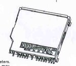
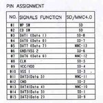
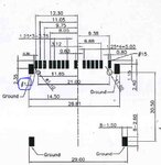
Can anyone help me checked my connector pin should connect based on schematic diagram SD/MMC connector I used ?
I'm confused I read it's datasheet description.

Here's the schematic diagram:
connector.JPGpin description.JPGSchematics Diagram 2.JPGDiptrace Diagram_Revised[19 August 2011]_USB_A_MALE_SWITCH.JPG

Last diagram 's my own SD/MMC design schematic.

Regards
Linspire
 

Status
Not open for further replies.

Similar threads

Part and Inventory Search

Welcome to EDABoard.com

Sponsor

Back
Top