jegues
Member level 3

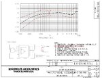
I've just now started to check how my circuit meets the other requirements desired within the design such as the frequency response, input/output impeadance etc...
I tried ranging the frequency from 1kHz to 3kHz and there was no noticeable effect on my amplifiers gain or functionality, so I deemed it capabale of provided the desired frequency response.
Now I've been trying to measure my input and output impeadances but I've been struggling a fair bit.
I originally tried measuring the input and output impedance using the tests described here,
**broken link removed**
But when I was to measure voltages such as V1 and V2 for a known resistance to find the input impeadance, the measurements I found on the meters would vary all over the place, making it hard for me to select a value in which to compute my input impeadance.
I had similiar issues when attempting to preform the approriate tests to determine the output impeadance.
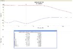
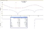
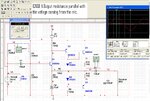
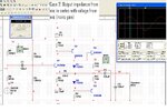
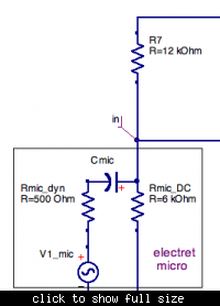
Is it possible to determine these two quantities by simply measuring the resistances at the respected input/output terminals as I have done in the figures posted below?
If this is indeed the case, then I have some more tweaking to do within my circuit to meet the input/output impedance requirements specified in the design. How can I do such a thing without ruining the desired gain that I've established?
It could very well be that I am going about measuring/determining the input/output impedances the wrong way, if that is indeed the case please let me know.
Thanks again!


