earckens
Junior Member level 2

- Joined
- Aug 25, 2016
- Messages
- 21
- Helped
- 0
- Reputation
- 0
- Reaction score
- 0
- Trophy points
- 1,281
- Location
- Ghent
- Activity points
- 1,433
EDIT: I am not sure this was posted in the correct subcategory?
A simple circuit with a MAX485 (attachement 1) works perfectly when used in a breadboard setup. However, as soon as the test is transferred to a fabricated pcb this circuit does not work.
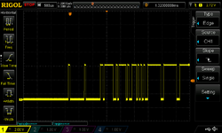
1. The RS485 link receives valid data which is correctly parsed in the breadboard dcircuit. The RX line receives data (see attachment 3: scope printout), the DE line is properly pulsed when TX wants to send its reply. The master acknowledges receipt.
2. However, when using the PCB design (attachment 2), RX is still properly received at slave controller level (stil same image as attachment 3) but DE does not respond: level stays low, ie no intention to transmit.
Same software, same controller.
When reverting back to the breadboard setup all functions as should be.
When in breadboard modus I connected DE from the breadboard setup to the PCB (with a MAX485 soldered in place, under power: all still ok (to make sure there are no PCB issues with the DE line).
When removing the soldered MAX485 from the pcb for testing: it functions well, all ok.
I am "end of line" after two days of testing; any help would be very greatly appreciated!
Code:
/* http://www.utrainia.com/65-arduinocmri-and-rs485
/* Arduino CMRI and RS485
*/

#include <Auto485.h>
#include <CMRI.h>

#define CMRI_ADDR 0

#define    DE_PIN 2
#define   LED_PIN 13

Auto485 bus(DE_PIN); // Arduino pin 2 -> MAX485 DE and RE pins
CMRI cmri(CMRI_ADDR, 24, 48, bus); // defaults to a SMINI with address 0. SMINI = 24 inputs, 48 outputs

void setup() {
  pinMode(LED_PIN, OUTPUT);
  bus.begin(19200);
}

void loop() {
  // 1: main processing node of cmri library
  cmri.process();

  // 2: update output. Reads bit 0 of T packet and sets the LED to this
  digitalWrite(LED_PIN, cmri.get_bit(0));

  // 3: update input. Flips a bit back and forth every second
  cmri.set_bit(0, (millis() / 1000) % 2 == 0);
}
Attachments
Last edited:

