Continue to Site

Welcome to EDAboard.com

Welcome to our site! EDAboard.com is an international Electronics Discussion Forum focused on EDA software, circuits, schematics, books, theory, papers, asic, pld, 8051, DSP, Network, RF, Analog Design, PCB, Service Manuals... and a whole lot more! To participate you need to register. Registration is free. Click here to register now.

lumped network does not provide matching

Status
Not open for further replies.
Hi All,
i have a question regarding the vna i am using.
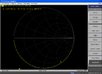
after calibration of the vna we will check it whether that is correct or not by looking at the smith chart.
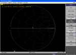
so on looking on it after connecting a 50 ohm(same used in the calibration kit) load it shows a point at the centre.
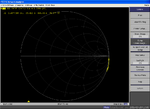
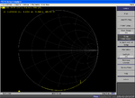
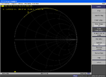
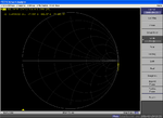
but at the same time i was checking it's behaviour at the open condition it is supposed to be at the right corner of the horizontal line. if not then it should so some high impedance,but it is not.

without connecting anything on the cable it shows the impedance of -33+j(-2000) @1Ghz and (-7-j279) @8Ghz(calibration frequency range).

and on using the open load from the calibration kit it gives (0.1-j245)@1Ghz and (0.03+0.62)@8Ghz
is something wrong with my calibration.

i have done same thing using different cables.is it correct behavior. because for open load condition the impedance should be high. for short load condition the impedance is very low so that is understandable.am i correct to think that the impedance will be very large like in kohm for open ckt condition

- - - Updated - - -

i am using feq range of 1-8ghz for calibration.
 

Impedance numbers aren't very informative. Just consider that open and short are rotated (somewhere near the unit circle in Smith chart) when changing the cable length. 50 ohms stays in the center and real loads ≠ 50 ohms move at circles around the origin.
 

see the image below for open load(used for calibration) connected to the vna.

- - - Updated - - -

is this response correct?

- - - Updated - - -

also the response with no load connected(open condition) and matched load.

sir if this is correct can you give me some explanation why for the open load condition the impedance seen is so low. it should be in kohms for very high impedance conditions
 

Attachments

  • 2cal_op_kit.PNG
    2cal_op_kit.PNG
    31.9 KB · Views: 60
  • open_without_load.PNG
    open_without_load.PNG
    30.2 KB · Views: 61
  • match_load.PNG
    match_load.PNG
    29.9 KB · Views: 58

That's good example how the open load s11 is rotated when the reference plane is different from calibration. Any real load s11 (e.g. of your antenna) would be also rotated. If you make your antenna measurement with an incorrect reference plane, you get a wrong impedance values.

Try to apply port extension to rotate open load s11 back to +1. Similarly you can use port extension to move the reference plane to the actual antenna terminals.
 

sorry sir,
i am getting confused now.

1. are you saying that the calibration plane is different from the plane where the load measurements are taken.
but why because these are the same load which i used for the calibration.(if there is no change in the setup why this change will b there? these are the results when calibration kit loads are measured)

2.also if this is the case means it is wrong and should no be used for measurement, then if the planes were same in that case how the variation would have been ? would it be like a point just like the case of 50 ohm impedance( or a trace like i am getting now but very high impedance)

3. what to you mean by making s11=+1, because already even for these cases the s11 is very close to 0 db(in the log magnitude plane). so basically have to adjust in such a way that the zin in high for the open cky condition
 

I don't know how the open load cases in post #23 have been exactly measured, but obviously the cable length ("reference plane") has changed between calibration and measurement. |s11| = 1 (or 0 dB) is maintained but complex s11 is rotated around the unit circle and impedance numbers are changing respectively.

This is very basic RF stuff, I can't imagine using a VNA successfully without understanding it.
 
okay got it.
so basically the s11 should also be almost like a circle(like a point ) for open load condition. all i need to do is to make sure that after the connection for measurement the open load response should be like the matched one (a point ) in the 0 degree at the unit circle. correct
 

Yes. You should make sure that at the cable position where you want to make the impedance measurement open circuit displays as s11 = +1 (or short as -1).
 
the response for the open short and load condition after the calibration which uploaded i send to the tech support team also from where i rented the NA, they are saying that the responses are actually correct. when i explained the concept which you gave they told that is correct but at the same time the response is there because it is not possible to achieve a perfect open, some small capacitance will be there and also the change in the plane concept that you told.

- - - Updated - - -

if what they are saying is indeed correct then i should have been able to the implement the matching network and get the desired response.

- - - Updated - - -

these are the screenshots which sent
 

Attachments

  • matched load connection.PNG
    matched load connection.PNG
    29.9 KB · Views: 71
  • open load connection.PNG
    open load connection.PNG
    30.3 KB · Views: 74
  • short load connection.PNG
    short load connection.PNG
    30.2 KB · Views: 70
  • without any load connection.PNG
    without any load connection.PNG
    29.5 KB · Views: 61

Status
Not open for further replies.

Part and Inventory Search

Welcome to EDABoard.com

Sponsor

Back
Top