yefj
Advanced Member level 5

- Joined
- Sep 12, 2019
- Messages
- 1,552
- Helped
- 1
- Reputation
- 2
- Reaction score
- 5
- Trophy points
- 38
- Activity points
- 9,349
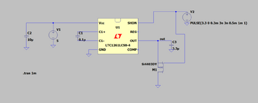
Hello , I am trying to implement the response of DC-DC circuit shown in the attached link.
Its a pure simulation functionality issue.
I put a pulse into SHDN which in real life will be GPIO periphery of MCU.
As you can see when I put 3.3V the DC-DC is not responding.
When SHDN=0 its start working and after some time settles to -4V.
The problem starts when I put 3.3V back to SHDN ,the output just stays as it was before.
As you can see below I have tried to put MOSFTER to discharge quickly the output.
The discharge is working but I get -0.8V instead of -4V and i get a muc bigger ripple.
Where did i go wrong?
Thanks.
https://www.analog.com/en/products/ltc1261.html?ADICID=SYND_WW_P682800_PF-octopart
https://www.qorvo.com/products/d/da007774


