
--BawA--
Advanced Member level 1

- Joined
- Nov 28, 2012
- Messages
- 479
- Helped
- 43
- Reputation
- 86
- Reaction score
- 42
- Trophy points
- 1,318
- Location
- Noida, INDIA
- Activity points
- 4,931
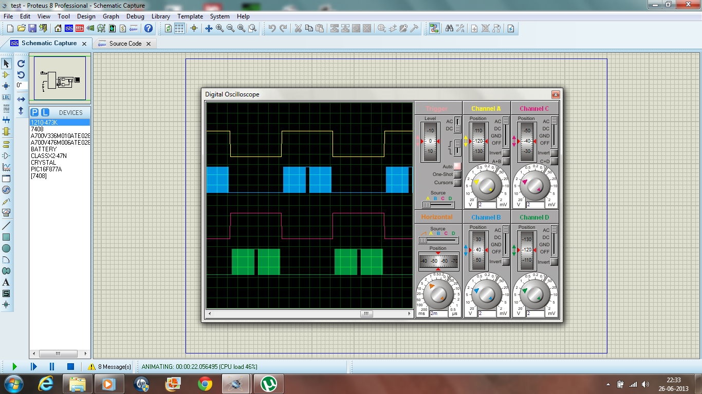
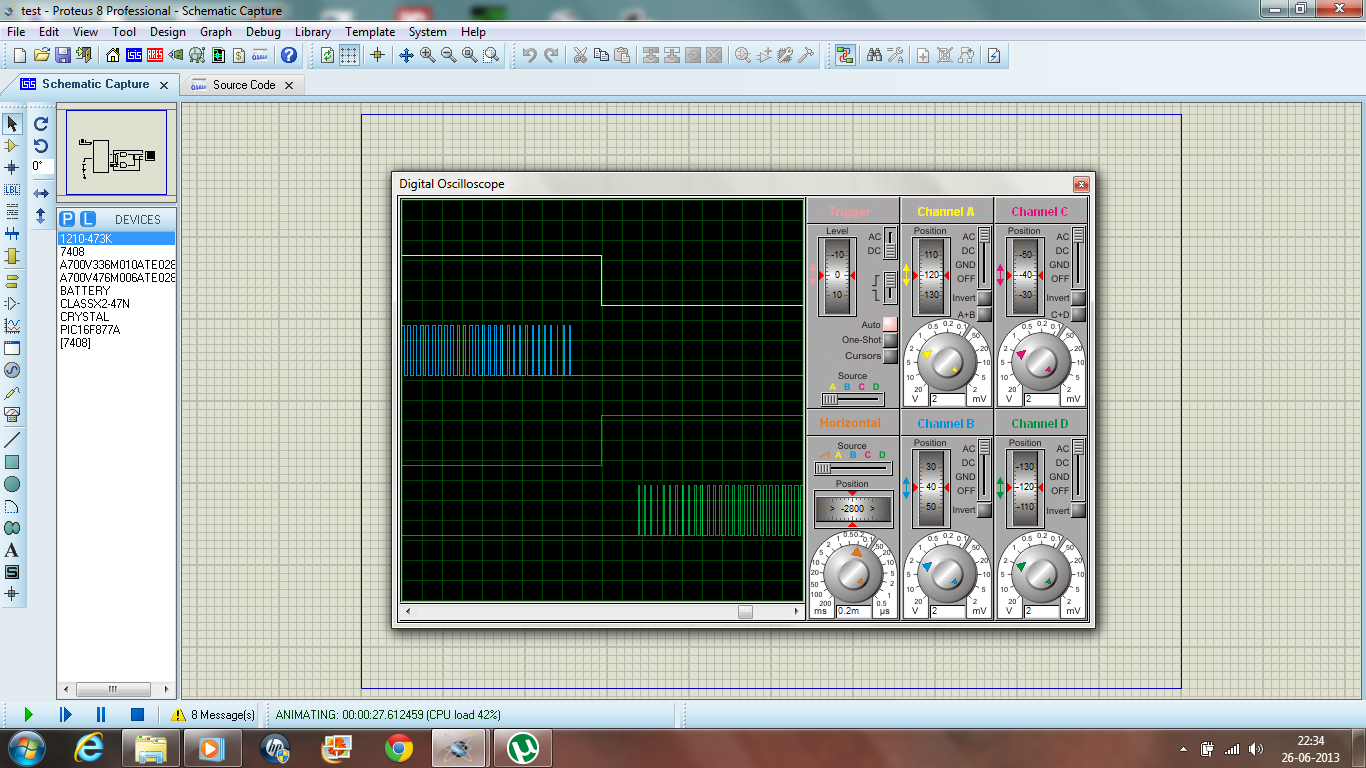
ahsan_i_h said:In these pdfs one of the arms of H bridge is driven by 50Hz and other arm is driven by PWM signal.
But, perhaps, In your design top mosfets of the arms are getting 50Hz signal and bottom mosfets of the arms getting PWM
signal (but 10ms alternately). Is that right ?
If it is right, then your filter requires a minimum load current to work as expected.


I think you are still using elctrolytic capacitor in filter output which you are not mentioning and which is the killer.my inductor as suggested by FvM,, i have made it to 5mh , and also used 0.22uf capacitor
i have used an lc filter in output of the bridge rectifier , 3mh inductor and 47uf electrolytic capacitor,also i have added two 0.1uf ceramic capacitor in parallel to electrolytic capacitor

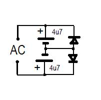

I don't think that the filter uses an electrolytic capacitor
Can we use electolytic capacitor to design a low pass lc filter for filtering spwm from h bridge ?
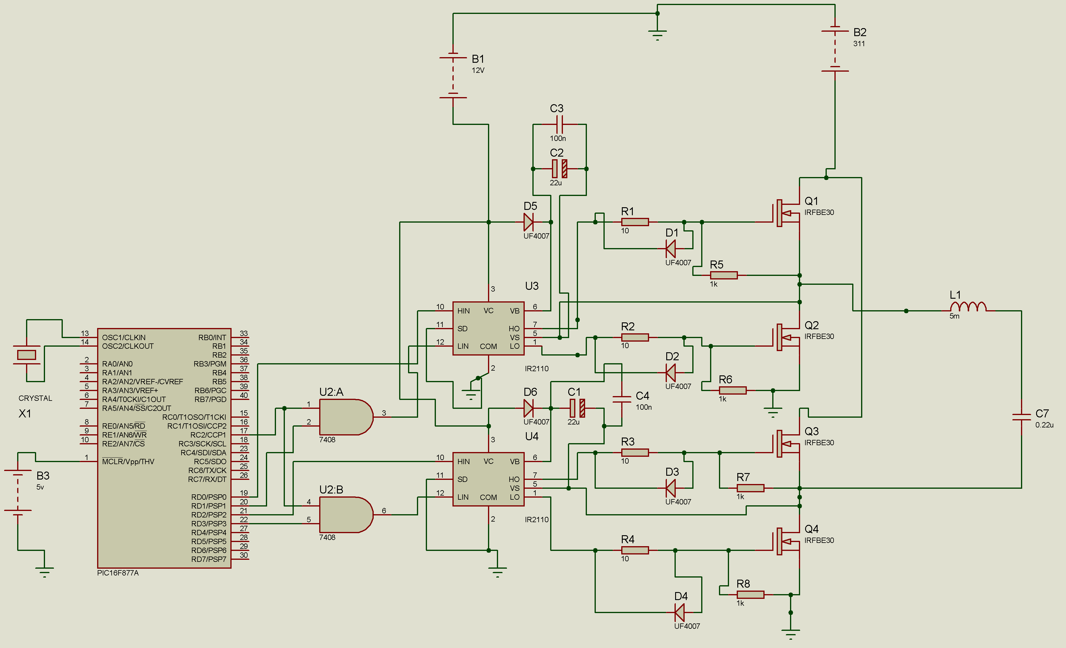
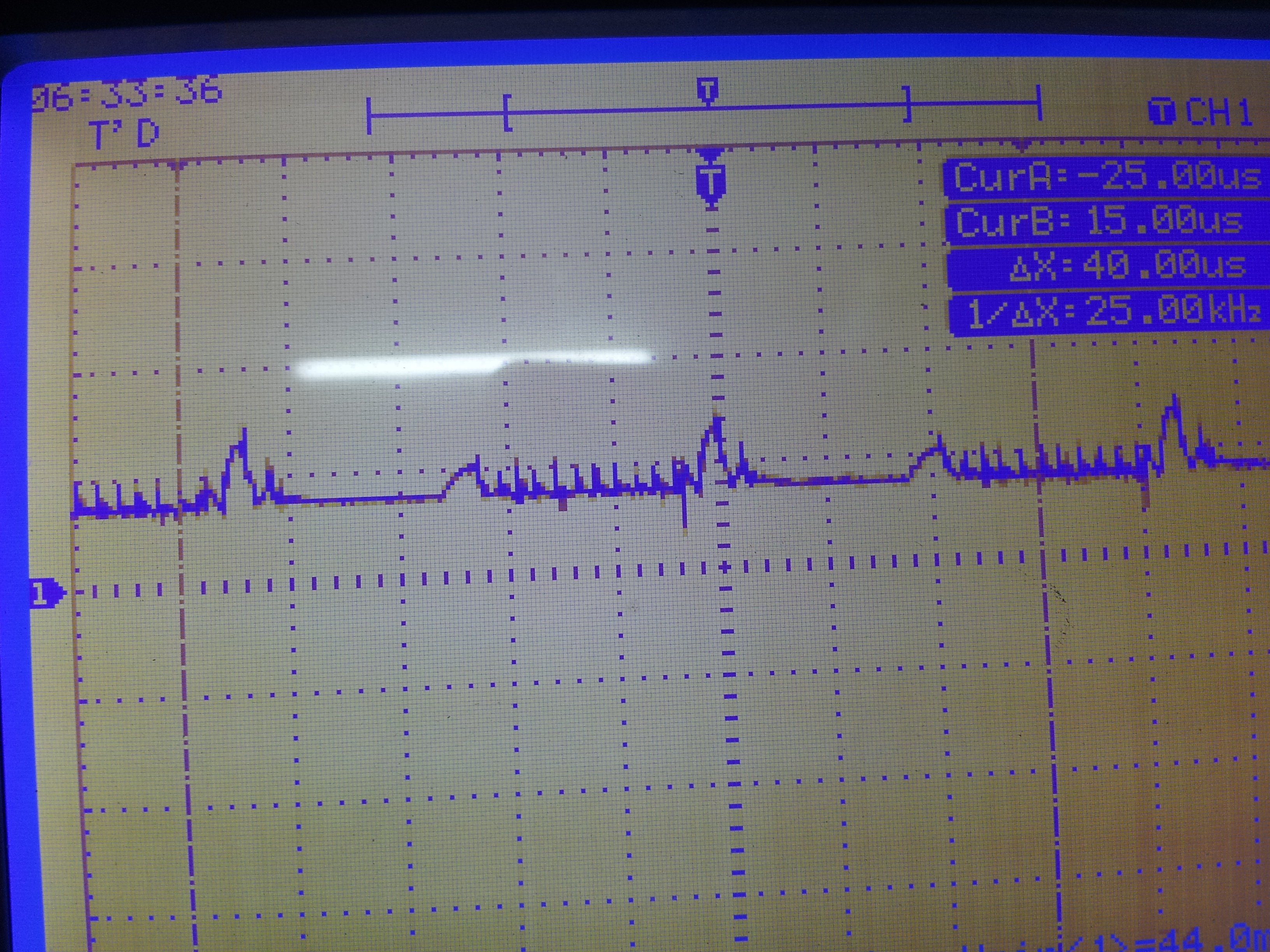
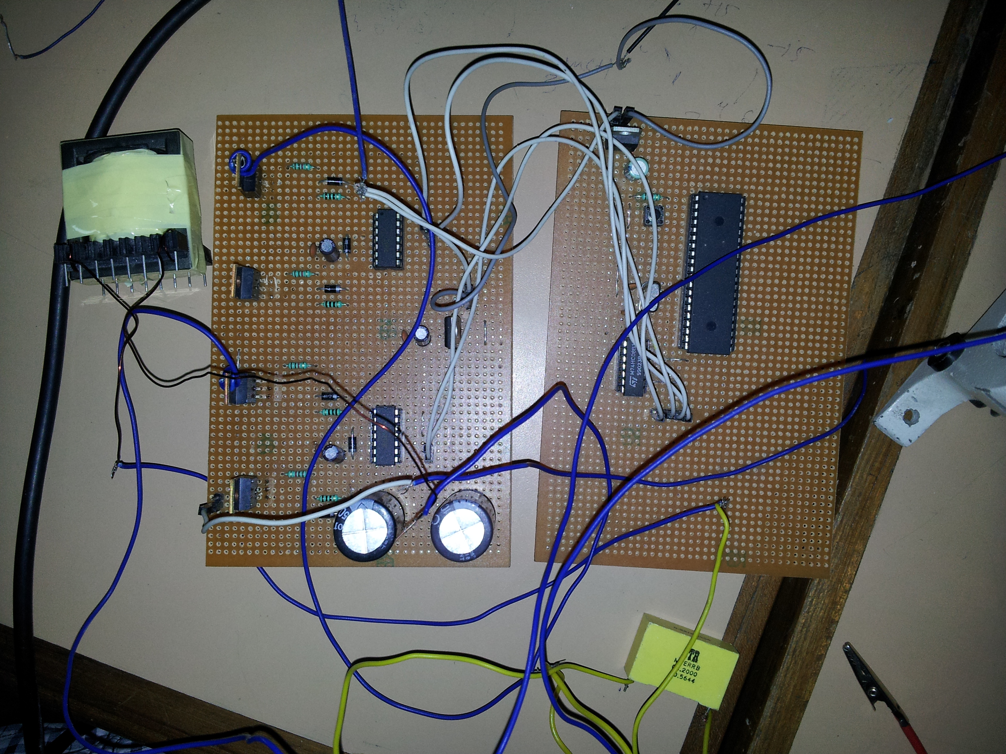
How to reduce parasitic circuit inductance ?FvM said:Looking at the strip board setup in post #41, I imagine problems caused by parasitic circuit inductance and possibly insufficient bypasing.
We can't see the actual wiring on the stripboard bottom, so it's partly a guess. But shorter and wider traces or most likely required.How to reduce parasitic circuit inductance ?
I didn't see any VCC/COM bypass capcitors near the IR2110. By the way, there are no IR2110 Vss pins connected in the schematic.And what do u mean by insufficient bypassing?
In my actual design I hve grounded the COM pin.FvM said:I didn't see any VCC/COM bypass capcitors near the IR2110. By the way, there are no IR2110 Vss pins connected in the schematic
FvM said:We can't see the actual wiring on the stripboard bottom, so it's partly a guess. But shorter and wider traces or most likely required.
I was asking about Vss pin.In my actual design I hve grounded the COM pin.
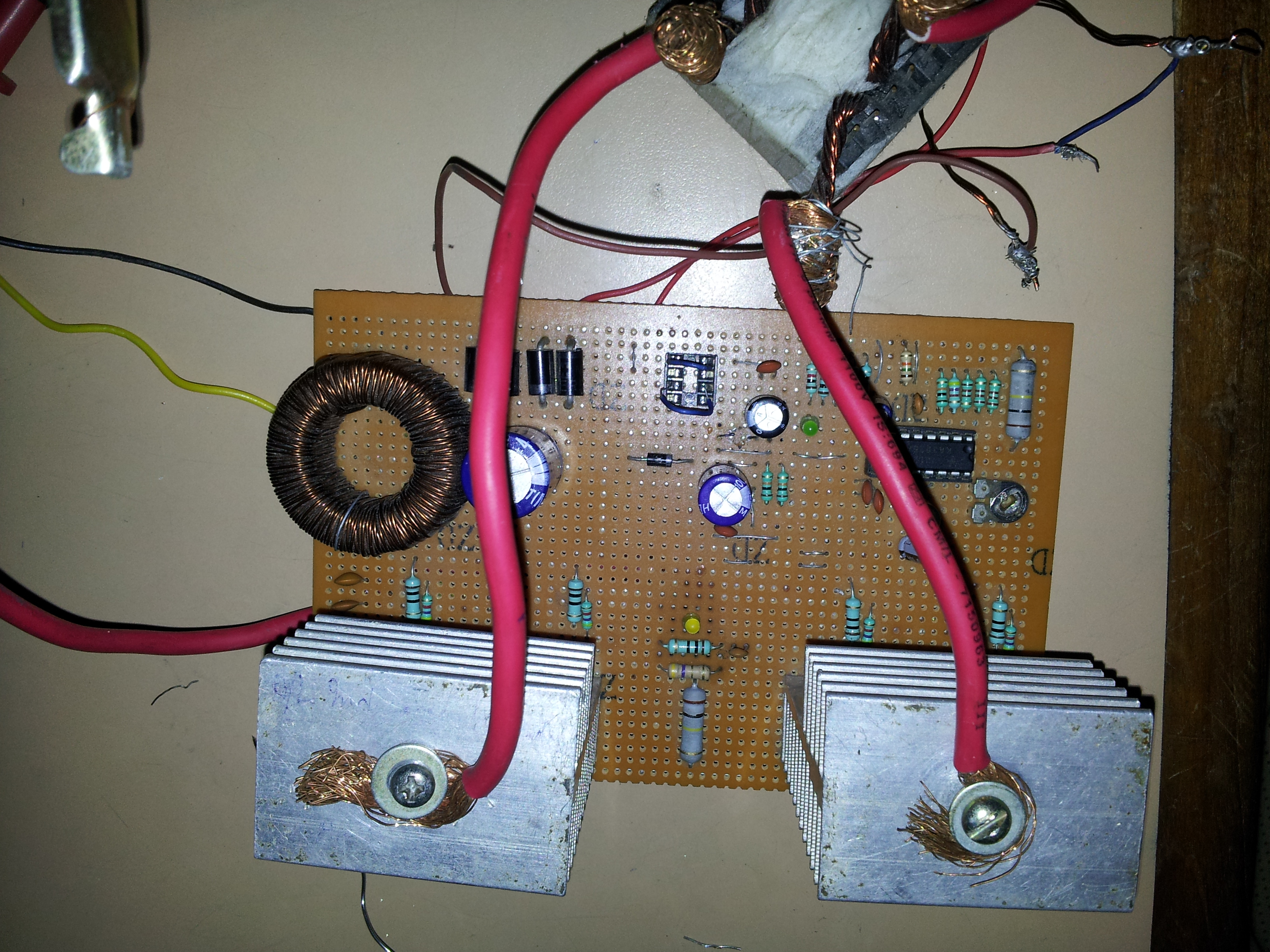
Why invent the wheel again? There are many application notes online for inverters, UPSs like IRF and microchip and other sites. There mostly inductors are used in both output legs ranging between 0.7-1.2 mH AND 2.2uF to 4.7uF filter capacitor. Of course these valued depends upon voltage, frequency, output power. For 240V, 16-20KHz, 300-600 watts, the values fall in this range.I hve used 5mh inductor , 0.22uf capacitor

We use cookies and similar technologies for the following purposes:
Do you accept cookies and these technologies?
We use cookies and similar technologies for the following purposes:
Do you accept cookies and these technologies?