Continue to Site

Welcome to EDAboard.com

Welcome to our site! EDAboard.com is an international Electronics Discussion Forum focused on EDA software, circuits, schematics, books, theory, papers, asic, pld, 8051, DSP, Network, RF, Analog Design, PCB, Service Manuals... and a whole lot more! To participate you need to register. Registration is free. Click here to register now.

Low Parts-Count, Low Heat, 4A, SMD Current Regulation?

Status
Not open for further replies.

theboom

Member level 2
Member level 2
Joined
Jun 4, 2022
Messages
47
Helped
1
Reputation
2
Reaction score
0
Trophy points
6
Activity points
281
My application is a single-cell lithium battery charger. I assume constant-voltage with current-limiting would work (but i may be mistaken).

There will be a group of disconnected cells (not a battery pack). All the cells in the group will be the same chemistry as each other. Need to support both Li-ion and LiFePO.

A single SMPS will supply regulated constant voltage for all the cells. So i think all that's needed is a current limiter on each cell.

The LM338 seems to have low-parts limiter, but apparently not available in SMD package, and (i'm told) not low-heat.

1654336499220.png


I found this current limiter for the TL431, but i'm told it will disconnect when limit is reached, rather than simply limit current to desired level.

1654336968675.png


If possible, I like the idea of shunting the excess current to other cells in the group, rather than wasting it as heat.

I'd be fine with a low-parts single-cell charger IC. Analog offers several, such as the LTM8026, but much too expensive for my application.

1654338919225.png
 
Last edited:

Hi,

I´m not getting emotional.

It´just that I miss calculations and true technical discussion. Ignoring voltage drop of series connected circuits ..heat generation...


If you hae a constant voltage .. folowed by a constant current circuit .. then the voltage isn´t "constant" anymore, it depends on the constant current circuit and it´s behaviour. As lang as you ignore this .. or at least tell how you want to achieve these functions .... how can we go on to find a solution?
I tried to explain this in post #6. There is a voltage drop druing "current limit" and there is another voltage drop when "not in current limit".
These are two systems interacting.

Where do you see the difference between current limiter and "constant current"?
The same for voltage.

It makes a difference if you connect a "constant voltage" circuit followed by a "constant current circuit" (= 2 regulation loops)
versus one regulation loop including U regulation and I regulation with one pass element. I also tried to explain this with the voltage drop in the current limiter stage.

****
I call myself rather experienced in designing electronics. In the past I´ve tried to do similar things than you do. In the end it always was a waste of time.
I always tried to go my own way. Thus I appreciate your "special" idea. But one can not ignore law of physics like Ohm´s law and Kirchhoff....

You misinterprete the "3A" rating of a voltage regulator as a "3A constant current" function. The "3A" means it is designed to drive loads at least up to 3A. The current limiter is not a clean regulated current limiter, it is just an internal overcurrent protection (thus rather coarse value of 3.5A.. 8.5A). It prevents the internal pass transistor from being killed and it ensures that the temperature rise is limited in a way that the overtemperature protection has enough time to react.

Again I have to repeat: Power disspation = heat. Power dissipation on a linear (non switching) system is: (always!)
P_tot = (V_in - V_out) * I.
It does not matter what parts you use.
The only way to reduce heat is to reduce V_In by using a suitable circuit that can work as current limiter while maintaining battery voltage.
I can not see how you achieve this

I already asked for a draft and some calculations....
I still miss these informations... and yes maybe this is why I don´t see how your idea can work.
If you want to go on with the discussion it´s important to give these informations.

How dare i!
This is emotional.
Designing electronics is not just "want" and "whish" ... it needs to be possible, comply with math and physics.

***
Thermal shutdown of the regulator does not prevent a LiIon battery to explode.
And thermal shutdown is not what you want to during normal operation. It rather is the last chance to protect from self destruction. If you operate an IC at this temperature you have increased aging in solder joints .. and the materail around.... and also the IC.

*****
Please draw a diagram with currents and voltages:
a circuit like [CV] --> [current limiter] --> [battery]
For a whole charging cycle:
* from zero battery voltage (fully discharged batter or bad battery)
* to zero chargincg current (fully charged battery)

Klaus
 
  • Like
Reactions: theboom

    theboom

    Points: 2
    Helpful Answer Positive Rating
By starting with a low supply voltage you reduce the amount of muss and fuss in designing the charger. This simple arrangement puts the 3.7v battery in the collector leg of a transistor. Say the discharged battery is at 3.2v, so charge rate is about 1 Ampere. The transistor dissipates about 1W as heat (hot enough to make you let go after gripping it between your fingers for a few seconds).

Then as battery voltage charges up to 4.2v, the bias resistor passes less current, causing charge rate to gradually taper to a minimum.

4.2v is commonly quoted as the maximum voltage to which you should charge a Li-ion cell. Higher than that is risking fire or explosion (as seen in numerous news reports). The key is to make your supply voltage 4.5 or 5v.

simple battery charge via NPN 3_7v bat in collector leg.png
 
  • Like
Reactions: theboom

    theboom

    Points: 2
    Helpful Answer Positive Rating
I miss calculations and true technical discussion. Ignoring voltage drop of series connected circuits ..heat generation...
i welcome that! I'm not a trained engineer. I'm here to learn, not ignore physics.

There is a voltage drop druing "current limit" and there is another voltage drop when "not in current limit".
I don't have a complete grasp of that yet, but i'm thinking feedback may be a way to adjust for drops.

Where do you see the difference between current limiter and "constant current"?
The same for voltage.
That may well be my misunderstanding. I'm (perhaps incorrectly) assuming the following:
  • constant current mode: current will remain fixed regardless of load, and voltage may change to keep the current steady. For example, when a cell is nearly discharged (say 3V3), then the voltage coming from the charger will drop down until desired current is reached. As cell charge-state increases, charger voltage increases to maintain the same current draw by the cell. The cell isn't prevented from pulling the current it wants -- rather, voltage is adjusted so the cell wants the amount of current we intend, eg 1C.
  • current limiting: voltage remains fixed (ie constant voltage) and current is allowed to shoot as high as it wants, until it hits the current ceiling. Then the cell is prevented, by the current ceiling, from pulling the current it wants.
  • constant voltage: voltage remains fixed, and current changes to keep voltage steady. Eg, at the tail end of a charging cycle, voltage is held steady at ~4.2V, and the cell draws less current since it's charge-state has almost reached the constant voltage coming from the charger. The cell isn't prevented from pulling the current it wants, but it's almost full, so it doesn't need much current.
  • voltage limiting: Not sure what this means.
1654493997228.png


You misinterprete the "3A" rating of a voltage regulator as a "3A constant current" function. The "3A" means it is designed to drive loads at least up to 3A.
No misinterpretation, I understand that.

The current limiter is not a clean regulated current limiter, it is just an internal overcurrent protection (thus rather coarse value of 3.5A.. 8.5A).
That i didn't know, but i didn't assume either way. I proposed the MIC35302 as a potential solution, not knowing if it would meet our need. Not sure why we're debating what i did or didn't understand. Let's stop talking about me.

Power disspation = heat. Power dissipation on a linear (non switching) system is: (always!)
P_tot = (V_in - V_out) * I.
It does not matter what parts you use.
It doesn't matter what parts you use? Is it not true that some parts can handle higher currents, while other parts will burn up?

The only way to reduce heat is to reduce V_In by using a suitable circuit that can work as current limiter while maintaining battery voltage.
I'll have to ponder that statement for a while.

thermal shutdown is not what you want to during normal operation
I agree, as I discussed above. Sorry if i was unclear.

* from zero battery voltage (fully discharged batter or bad battery)
For the moment, i'm setting aside the issue of recovery of an undervoltage cell. First i want to solve the main charging phase.
 

i welcome that! I'm not a trained engineer. I'm here to learn, not ignore physics.
please do calaculation using Ohm´s law, plus, minus.. multiply on your own.
Excel is a big help, especially when it comes to graphs.

I don't have a complete grasp of that yet, but i'm thinking feedback may be a way to adjust for drops.
Maybe here is the biggest problem. One can´t change the load (battery). Thus one only has voltage and current. To limit the current you have to change the voltage. There´s no way around.

current limiting: voltage remains fixed
impossible.

That i didn't know, but i didn't assume either way. I proposed the MIC35302 as a potential solution, not knowing if it would meet our need. Not sure why we're debating what i did or didn't understand. Let's stop talking about me.
See my text .. and see this (your) answer.
I did not point at "you".
you wrote 4x "I", you wrote "not knowing", you wrote "we" ... all referring to "you".
... but I´m not allowed to do the same.

***********
current limit, current regulation, constant current:
all do the same: below the "current limit value" they are rather low ohmic (low voltage drop) and above the limit they are rather high ohmic (high voltage drop). No current limit without voltage drop.

***********
The shown diagram misses the power supply voltage, the current limiter voltage drop, the currents.
This are the key values/parameters that describe the behaviour of serially connected devices.
***********
It doesn't matter what parts you use?
Correct. As written a couple of times including formula.

Is it not true that some parts can handle higher currents, while other parts will burn up?
It is true that different parts with different sizes, get different temperature rise .. even at same power dissipation.
This is called heat spreading.
A 50W soldering iron melts solder ... 50W on a home radiator generates barely noticable temperature rise.

For the moment, i'm setting aside the issue of recovery of an undervoltage cell. First i want to solve the main charging phase.
O.K. then form zero output voltage to full output voltage,

Klaus
 
  • Like
Reactions: theboom

    theboom

    Points: 2
    Helpful Answer Positive Rating
By starting with a low supply voltage you reduce the amount of muss and fuss in designing the charger.
Good news!

This simple arrangement puts the 3.7v battery in the collector leg of a transistor.
Thx for that! Am i to understand your circuit is a charger?

Does it fulfill the Limiter function here?

1654509812533.png


Will the bias resistor have to pass 1A?
 

Hi,

You should read about Li-ion battery charging, a little more in depth than you have. Monitoring voltages is a poor, inaccurate method, a meaningful cell charger would use a bi-directional coulomb counter. Li-ion have a very limited temperature range. They are best served with pre-charge (e.g. 100 mA) then full charge (e.g. 1 A).

Your 'low-parts' design of a voltage regulator or DC/DC converter and 'current-limiter' is too basic and runs the real risk of being a fire hazard.

You seem to enjoy winding people up, I'm not sure why you derive pleasure fron that behaviour. We understand each other perfectly well. Please desist.
 

You should read about Li-ion battery charging, a little more in depth than you have.
i'd like to suggest that a good way to avoid anyone getting wound up is if we not speak about people on a personal level. Please don't make assumptions about what i have or haven't read. Let's talk about cell charging.

Monitoring voltages is a poor, inaccurate method
Inaccurate method for what, specifically? Doesn't a charger need to monitor charge-state of the cell?

a meaningful cell charger would use a bi-directional coulomb counter.
Thx for that! Would it be correct to say that more than one commercial cell-charger on the market doesn't employ coulomb-counting?

According to what i've read (and my limited understanding), a coulomb counter is a kind of gas-gauge for a cell. It's concerned not with voltage but with amp-hours. It measures the rate of charge or discharge over a time-interval to estimate state of charge relative to the total amp-hour capacity of the cell when fully charged. When discharging, load-current is based on load-resistance. Is that correct? I'm guessing that, when charging, load-current is based on resistance of the cell?

1654556271260.png


This article mentions potential drawbacks of the coulomb-counting method:

"the CC method continues integrating errors caused by inaccurate measurements and other factors which can potentially generate a serious lack of reliability in the method."

The article suggests more intelligent model, which accounts for noise, age, and temperature.

"Bi-directional" means it counts while charging or while discharging. Is that correct? The application i've described in this thread doesn't involve discharging, just charging.


Li-ion have a very limited temperature range.
Do you mean while charging or discharging?

What aspect of this thread suggests i'm disregarding that concern?

They are best served with pre-charge (e.g. 100 mA) then full charge (e.g. 1 A).
Re pre-charge, are you speaking of slow recovery charge of a cell that has been over-discharged? I'm familiar with that concern. As i mentioned in the thread above, i'm temporarily setting aside that concern to first solve the main charge modes. If you have a chance, please read the previous comments above.

Your 'low-parts' design of a voltage regulator or DC/DC converter and 'current-limiter' is too basic and runs the real risk of being a fire hazard.
"Too basic" is too vague. What's missing?

Concerns like thermal monitoring are certainly essential to a safe charging system. For the moment, i'm temporarily setting aside those concerns to focus on the primary charging topology.

Once i have a good solution for the basic charging topology, then i will address other features.

You seem to enjoy winding people up
I have absolutely no intention of winding anyone up. I apologize if it seemed so. I'm here to talk about cell-charging. Please let me know specifically, precisely, exactly what i said that seemed provocative.

I'm not here to talk about my personality, my childhood, or anyone else's. To me, that's provocative and inappropriate. Let's focus on cell-chargers.
 
Last edited:

Hi,

I want to help people.
I don´t want to spread unpersonal information about cell charging.
It´s well known how cell charging works. It´s well known how series connections of electronic devices works. How to calculate it.
It´s well known how to calculate power dissipation and temperature rise.
It´s well known how do design cell chargers and waht to care for.

There are electronic schools, tutorials, university informations, design notes, application notes.
All the knowledge is aavailable for everyone, is for free, is given as documents and aften also as videos.

All is available, free, unpersonal.

A forum is for discussion. One people to the other.

The one needs information. Personally, because basically the information is already known and freely available.
It´s not so that one has to "invent" or "research" how to charge batteries and how to design electronics.
No, it is a personal thing to teach you this. Other people already know.

In a forum there are people who "give" informations and others who "gain" that informations.
The one spends time, effort, need to explain the same things again and again...
But where is the feedback?

It seems I´m not alone, who misses thankfulness, kindness, respect....

No one here gets paid for spending her/his time.
Give us a reason why we should continue to spend our time. Time for you. Solely for you.

Klaus
 

@KlausST I'm VERY GRATEFUL for all your help!

i directed the word "respect" to you in this thread. I've thanked various people, including you. And i thank you again.

Thank you especially for the suggestion to reduce power supply output voltage. That's extremely valuable and helpful! You are helping me approach a solution. You're awesome!

This circuit is related to my project to introduce disadvantaged teenagers to electronics. You're helping me help them.
theboom.org
 
Last edited:

Thx for that! Am i to understand your circuit is a charger?

Does it fulfill the Limiter function here?

Will the bias resistor have to pass 1A?

The bias resistor can be adjusted to charge the cell at any rate you wish (within reason). Its ohm value must be high enough so that it passes a few mA.

My simple transistor circuit is by no means a 'smart' charger. It's merely a handy trick to reduce charge current as battery voltage rises. It lacks sense to detect the health of a cell. It lacks safeguards (example, thermal sensing). LED's should be added to monitor progress. Etc.

It is better than charging a cell through a plain resistor in series with, say, a 10V source. And experimentation may reveal some better arrangement than mine.
 
  • Like
Reactions: theboom

    theboom

    Points: 2
    Helpful Answer Positive Rating
In the end I still think that a common power supply combined with individual CC/CV charging (IC) solutions is a good way.
Our ("our" refers to my project, not to the members of this thread) ideal part is:
  • low-cost (sub $2)
  • low parts (sub 5 parts)
  • available (Digikey, factory, or market)
  • 4A+ charge current
  • Active (not obsolete)
  • Can take the heat
  • Switched
  • Supports LiFePO4, or adjustable charge V, or multichemistry
I haven't yet found any part that meets these criteria. Below are the only active, available, sub-$2 charger IC's on Digikey that support LiFePO4. All are 1A. Some are low parts-count, but not all. All are linear, not switched.

PartVol PriceMin OrderPartsCurrentChemistryFreqNotesLink
MCP73123
$ 1.15​
1​
3​
1ALiFePO4 onlylinear"fast"https://ww1.microchip.com/downloads/en/DeviceDoc/22191E.pdf
BQ25180
$ 1.56​
1​
6​
1Amultichemistrylineardelivers system powerhttps://www.ti.com/lit/ds/symlink/bq25180.pdf
BQ25070
$ 1.21​
3,000​
10​
1ALiFePO4 onlylineardelivers system powerhttps://www.ti.com/lit/ds/symlink/bq25070.pdf
BQ25071
$ 1.57​
1​
12​
1ALiFePO4 onlylineardelivers system powerhttps://www.ti.com/lit/ds/symlink/bq25071.pdf
--- Updated ---

(Reminder: This is an investigation of basic charging algorithms and topologies. Circuits shown aren't a complete charging system. Hobbyists should employ safe charging practices, including monitoring the charge-state of cells. It's safest to use off-the-shelf chargers which include various protection mechanisms.)

as battery voltage charges up to 4.2v, the bias resistor passes less current, causing charge rate to gradually taper to a minimum.

View attachment 176666

Your design may provide the precise charging curve i seek:

Constant-current–constant-voltage (CC–CV) is one of the most widespread, because of its simplicity. Four new profiles were tested and compared to a reference. The results coming from the new profiles demonstrate a simultaneous improvement in terms of charging time and cycling life, showing the reliability of the implemented methodology in preventing Lithium plating.

1654673770600.png


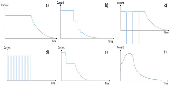
From this preliminary analysis, it was possible to develop new Multi-Stage Constant-Current profiles, designed to improve the performance in terms of charging time and cells capacity retention with respect to a reference profile. This kind of protocol is composed of two or more CC steps that end when a well-defined cut-off voltage is reached. [i believe the steps are trigged by defined cell-voltage levels]. The best result in terms of aging was obtained with MCC2. It can be observed that the MCC2 and the charging profile provided, among all tested profiles, the highest charge–discharge capacity during the execution of each aging step. The MCC Fast2, due to the different aging behavior, deserves a special further investigation.

1654673801828.png


Looking at the MCC2 current curve (b), it's looks like it starts with a long period at highest charge-current, then spends successively less time on each successively lower current.

To me, that looks like a quantized exponential curve. It looks like the current-curve on YOUR simple charger!

1654675264400.png


(PS, i could be wrong, but i suspect that those hobbyists who are starting fires by improperly charging their batteries aren't reading or posting to this forum.)
--- Updated ---

charge rate is about 1 Ampere. The transistor dissipates about 1W as heat (hot enough to make you let go after gripping it between your fingers for a few seconds).
Please share your math. Thx!
--- Updated ---

MCC2 source:
--- Updated ---

The key is to make your supply voltage 4.5 or 5v.
What if i kept my supply just slightly higher than the voltage level of the cell throughout the charge cycle? Would it draw the same amount of current, and charge just as fast, while the transistor would stay cooler?
 

Attachments

  • 1654675291033.png
    1654675291033.png
    4.6 KB · Views: 105
Last edited:

Hi,
Please share your math. Thx!
I´m still not sure how experienced you are.
According your habit ... it seems you are experienced.

But then you ask for math that is extremely simple:

P = (U_IN - U_out) * I. (as written several times now)
U_in = 4.2V (power supply)
U_out = 3.2V (Battery)
Thus (4.2V -3.2V) = 1V (voltage drop for current regluation, also written several times now.)
Now P = 1V x 1A = 1W

We tried to explain this. Several times.

This is basic electronics, physics and math.

I´m not sure where the problem is.
I can you tell my personal problem: I´m not patient enough to tell the same thing repeatedly. That's why I wouldn't be a good teacher. It tell it once. I see no feedback on this. Then I tell the same again. Also no feedback. Then it becomes difficult for me to tell the same again. Because I ask myself: "Why no feedback?" "Why not accepting it?" "Why not doing this simple math?"

I´m not the one, who want to do thers job ... and design a whole charger. Im not the one who wants to spoonfeed others ... by doing "4.2 - 3.2 = 1.0" or "1 x 1 = 1" for them.
I´m the one who wants to help other that show their effort. I want to suport those, who try to understand, read documents and refer to them, doing math on their own ..and I show them where the mistake is.
I want them to learn and understand for the future.

Klaus
 

@KlausST Thank you for writing out the math for BradTheRad's circuit.

I followed your recommendation to use an off-the-shelf charger chip. But i was unable to find an IC that met my requirements. I shared details about the only chips i found within my target price-range.

Therefor, i think it's legitimate to explore alternate charge methods. You made no comment about that.

It´s well known how do design cell chargers and waht to care for.
There are electronic schools, tutorials, university informations, design notes, application notes.
All the knowledge is aavailable for everyone, is for free, is given as documents and aften also as videos.
You imply there's but one way to charge lithium cells, and one must simply educate themselves about that one way.

But i shared above an academic research paper describing several alternate charging profiles, some showing superior performance to the standard CC-CV profile that's typically used in charging chips.

Therefor, i think it justified to explore alternate charging topologies.

The legitimate research i shared seems to contradict your assertion that there's but one way to charge lithium cells, and one must simply educate themselves about that one way.

But you have no response to the very relevant topic of alternate charging profiles.

I´m still not sure how experienced you are.
Why does that matter? Does this board require that i must have, or mustn't have, a certain amount of experience?

Why can't we simply remain focused on the discussion, and stop talking about me?

P = (U_IN - U_out) * I. (as written several times now)
But i cannot find this or any formula for P anywhere in this thread. I'm sure it's my blindness. Please link to any one of the several times it was written out.

Update: i found just once where you shared this formula. In Comment #21. You used a different notation.

P_tot = (V_in - V_out) * I.
I'd like to suggest that, in math, it's helpful to use consistent notation. Perhaps the other several times you wrote it out, you used yet another notation.

I'm not familiar with U notation. I just learned it's a German thing.

Germans took freedoms and started calling voltage "U", probably since that letter was largely unused and so couldn't be confused with anything else. They also came up with etymology: U is for Unterschied, which is German and means "difference"; very fitting since voltage is obviously the same as potential difference.

I´m not patient enough
I don't want you to feel vexed. You are free not to participate in this thread. No one is forcing you,. You are a free person. Be free.
 
Last edited:

Why does that matter? Does this board require that i must have, or mustn't have, a certain amount of experience?

Why can't we simply remain focused on the discussion, and stop talking about me?
It does matter.
Do I have to explain the voltage bevaviour of in series connected electrical devices or not?
..and the current behaviour?
Are you able to apply Ohm´s law or not.
(until here - post#33 - I´m not sure. I´ve not seen that you are familiar with these basic rules. Sometimes you contradict them. And I don´t know why.)

It´s a forum. You are an individual. And you asked the question. And some of your ideas don´t follow the rules of physics.
So we can´t ignore your "ideas" and your "state of knowledge" and so on.
"You" are a big part of whether this application will work or not.

There is no need to be perfect. Every one makes mistakes ... and mistakes are a part of a learning phase.
I´m surely not perfect an surely make a lot of mistakes. Every day. You can see many of my mistakes in this forum. And - hopefully - every time someone corrects me.. get´s back a big and honestly meant "Thank you" for improving my knowledge.
Nobody here gets blamed on mistakes or on a lack of knowledge. If you see something like this: Please use the "Report" button, so we moderators can stop it.

A discussion is not a "master--> slave system" nor a "one way question --> answer system". We also need your feedback, to adjust / refine our answers to give you best assistance. And that´s tuely what we want.

Klaus
--- Updated ---

You imply there's but one way to charge lithium cells, and one must simply educate themselves about that one way.
Surely not! I´ve never forced you to focus on "one charging method". This is completely against my conviction. Charging batteries is as old as there are rechargable batteries.
There are many ways shown in the internet. Each has it´s benefit and drawback.
It´s your idea, so it´s your job to read through them. Find out wha´ts suitabe for you and what is not.

But physics has rules. And when I see no solution to your idea I honestly tell this.
You may find it more kind/polite to support you on an idea ... but isn´t it a waste of time and money for you if I hide the truth?


But i cannot find this or any formula for P anywhere in this thread.
basically post#3
it also is used in post#6
and as text:

Do you understand that we need feedback ... instead of ignoring our informations?

U or V: I´ve been educated using U. For decades now. I don´t know where you live.
But yes, in an international forum one should use "the standard". Is "V" the only alloed standard?
What about inch vs mm, or HP vs kW ....

--> feedback can solve misunderstandings.

I'd like to suggest that, in math, it's helpful to use consistent notation.
I agree with you.
The problem here is that I don´t know your state of knowledge. Can you understand and use Ohm´s law? Are you familiar with abbreviations, do you prefer text?
We don´t know. You don´t show. So we are not able to adjust.

It´s like a regulation loop with broken feedback. The output will go to extremes. Unusable.

Klaus
 
Last edited:

One last word...

It's interesting how you quote my posts on the forum and pretend to be grateful...but in the back you start a report complaining about every one of my posts.

But now I get it. I won't bother you again.

Klaus
 
What if i kept my supply just slightly higher than the voltage level of the cell throughout the charge cycle? Would it draw the same amount of current, and charge just as fast, while the transistor would stay cooler?
@BradtheRad To answer my own question, based on helpful explanations in this thread, i think the answer is:

The larger the difference between Vcharge and Vcell (SoC), the higher the current draw and faster the charge.

So, i think the trick is to find the balance between fast charge (with high Vcharge) and low dissipation (with low Vcharge). Right?

It was said earlier in this thread that reducing heat requires LDO + lower Vsupply. But won't a lower Vsupply reduce heat even without LDO.

The transistor dissipates about 1W as heat (hot enough to make you let go after gripping it between your fingers for a few seconds).
i assume the critical factor is the transistor's ability to handle the heat. That's to do with the device's construction and physical characteristics. Some can tolerate 1W, some can't.

About this title, "low heat" -- not exactly accurate. I don't care how hot things get, as long as the components can handle it.


Is it necessary to bias the transistor in this application?
 

Yes transistors in linear regs always need biasing.
You dont want vin too low especially of the source is distant from the converter......low v means high i in the disty wires....keep voltage high as far as poss.

12V wouldl be a nice vin for a 3.5-4.3v cell....you could use a sync buck....but if you want low parts......it'll be expensive linear or maxim chip at 4A.

What is your primary power source?....mains?
 
  • Like
Reactions: theboom

    theboom

    Points: 2
    Helpful Answer Positive Rating
Great tips! But am i correct that we'll reduce dissipation if we lower the supply V going to the current regulator?

Yes transistors in linear regs always need biasing.
Normally, a bias resistor goes from V+ to Base, correct?

In the circuit given, there is one -- with the battery in between.
1655059421959.png


Should there still be an additional Rbias?

You dont want vin too low especially of the source is distant from the converter......low v means high i in the disty wires....keep voltage high as far as poss.

12V wouldl be a nice vin for a 3.5-4.3v cell....
What distance is too far? I'm thinking to place a V regulator giving 5V close to a group of cells, to reduce drop at each cell. Then a higher V (12V - 24V) will serve many groups from a distance. So we get the best of both worlds: low V close to the nodes to reduce dissipation, high V far from the nodes to reduce i.

1655060440917.png


you could use a sync buck....but if you want low parts......it'll be expensive linear or maxim chip at 4A.

What is your primary power source?....mains?
The higher V is coming from a mains wall-wart.
 

First consideration is safety -


Then maybe price -

Digikey pricing is not the last word in pricing unless you are doing very low volume
one-off design. Use it as a gross indication, and once you find functionality,
packaging, performance then you pick up the phone and call the vendor and discuss
with them. Key questions about real pricing, device lifetime will get answered. You
might even find there is a newer, lower cost, better solution when talking directly to
the vendor.

Device choice -

No one, to the best of my knowledge, wants a design with the highest parts count or
price. Unless you are a government economist trying to recover from a depression.
Such as was done in the Great Depression, eg. slaughter of farm animals to reduce
supply and recover pricing.

Focus on safety, functionality, cost, availability will serve you well. More or less in that order.


Regards, Dana.
 

First consideration is safety -
Thx for perspective! As i mentioned above, i will address safety. But my first objective is to work out the basic charging topology. There are many ways to charge a group of cells. Imo, solving the core functionality before adding safety measures is a logical development sequence.

once you find functionality, packaging, performance then you pick up the phone and call the vendor
i agree that Digikey is just a starting place. No doubt a device can be had cheaper in volume, or another vendor, or in direct negotiation with the manufacturer.

No one, to the best of my knowledge, wants a design with the highest parts count or
price.
It's sounds like you're saying "All designs and IC's with a given function will cost the same, and have the same number of parts." It seems to me that different IC's or circuits vary widely in COG and/or number of parts.

Do you have specific circuit or IC suggestions?

Thx again!
--- Updated ---

@cupoftea The intermediate 5V regulators in my last post would have more room/budget for larger components and heatsinks. Goal is to minimize footprint/parts/cost/dissipation at cell-nodes.
 
Last edited:

Status
Not open for further replies.

Part and Inventory Search

Welcome to EDABoard.com

Sponsor

Back
Top