Continue to Site

Welcome to EDAboard.com

Welcome to our site! EDAboard.com is an international Electronics Discussion Forum focused on EDA software, circuits, schematics, books, theory, papers, asic, pld, 8051, DSP, Network, RF, Analog Design, PCB, Service Manuals... and a whole lot more! To participate you need to register. Registration is free. Click here to register now.

Lcd interface with 89c51

Status
Not open for further replies.
there are some tips.

Use decoupling capacitor with your supply.
Ground pin 1 and 3 of lcd.
Check your connections to lcd twice.
 

i am using LCD on its back

ec1602j ver00 printed on pcb

and a sticker on which

ec016002
vybbl1
06.12.09

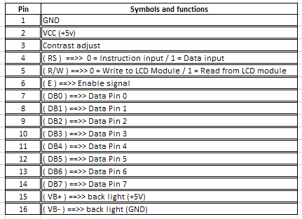
it is 16 pin lcd i think i am making mistake in connecting its pinout with microcontroller

i am considering this is the pinout of the lcd

28_1324648805.gif


please correct me if i am wrong.

---------- Post added at 19:33 ---------- Previous post was at 19:01 ----------

i grounded there is a change the second line of the lcd is filled with block but there is no "ABCDEF" message in first line ......
 

Is your simulation works fine?
Usually LCD have hd44780 controller on its back.

Above pin connections are correct.

Post your circuit image.
 

you should connect the pull up resistors of about 2.2k ohms with data pins of LCD and p1 of controller. because 89c51 have sinking ports and even can't blink an LCD if you connect it with port and to the ground. so the pull up resistor is must to make lcd working properly.

in your schemetic the other end of 22pf capacitors connected to the +Vcc should be grounded.
 

Hello,
First thing you need to learn is that real world is really different from simulation world.. Things which are working in simulator may not work well in real world.. there are many reasons!!!
What the main problem with lcd is to initialize it, to set proper delays, (means your lcd must know what microcontroller is sending to it, is it read signal,write signal, data ??) They all will get mixup if you dont send them with proper delays(time which is required by lcd to process and execute one command).. So to avoid these situation what you have is Busy pin.. it tells micro that lcd is still processing first code and is busy, so micro will send its next command when the busy Pin is clear.. This is the best method to initialize lcd.. here is the Working Code :

Code:
#include<reg52.h>
#define ldata P1 //16x2 lcd data pins to port p1
sbit en = P2^2;
sbit busy = P1^7;
sbit rs = P2^0;
sbit rw = P2^1;
void lcdcmd(unsigned char l);
void lcddata(unsigned char l);
void MSDelay(unsigned int t);
void lcdready();
void main()
{
while(1)
{

unsigned char message[] = "Hey.. ;) My$elF Tushki7 :)";
unsigned char z,l;
lcdcmd(0x38);


lcdcmd(0x0E);

lcdcmd(0x01);

lcdcmd(0x06);


for(z=0;z<25;z++)
{
l = message[z];
lcddata(l);
MSDelay(1275);
}
}
}
void lcdcmd(unsigned char l)
{
lcdready();
ldata = l;
rs = 0;
rw = 0;
en = 1;
MSDelay(1);
en = 0;


return;
}
void lcddata(unsigned char l)
{ lcdready();
ldata = l;
rs = 1;
rw = 0;
en = 1;
MSDelay(1);
en = 0;
return;
}

void lcdready()
{
busy = 1;
rs = 0;
rw = 1;
while(busy==1)
{
en = 0;
MSDelay(1);
en = 1;
}
return;
}
void MSDelay(unsigned int t)
{
unsigned int i,j;
for(i=0;i<t;i++)
{
for(j=0;j<50;j++)
{}
}
}

Good Luck :twisted:
 

what do you mean by not working. if you means there is no response from lcd then you have to check and resolder the connections of the lcd.

and if your LCD module has light with dark squares in both line then reduce the contrast of the lcd using the variable resistor connected to VEE (contrast adjust) pin of the lcd module.

for software problems check for lcd initialization carefully and must put required delays between commands and data send to the lcd module.

regards
 

Status
Not open for further replies.

Similar threads

Part and Inventory Search

Welcome to EDABoard.com

Sponsor

Back
Top