Continue to Site

Welcome to EDAboard.com

Welcome to our site! EDAboard.com is an international Electronics Discussion Forum focused on EDA software, circuits, schematics, books, theory, papers, asic, pld, 8051, DSP, Network, RF, Analog Design, PCB, Service Manuals... and a whole lot more! To participate you need to register. Registration is free. Click here to register now.

kelvin type Ohm Meter

Status
Not open for further replies.
@Klaus
I got to look at the datasheet and your opinion looks promising.
I want to know that I also need to calculate the current in a shunt that is also connnected in the circuit with the DUT Device as the known value of the shunt is important to calculate the resistance of DUT,So can I just measure the voltage drop across PFET DRAIN and SOURCE TERMINALS.
 

Hi,

you have to measure the DUT voltage drop directely at the DUT... kelvin type.

******

With the current source there usually is no need to measure the current, becuase it is fixed with "VREF" and "R" (according the schematic)
To dectect whether the current source is in regulation you may use a comparator at the OPAMP output. If the voltage is below 0.5V then it is most likely out of regulation (error!).
The 0.5V threshold depend on OPAMP_output_low voltage.

******

But for sure you can additionally measure the voltage across "R" to determine the current.
If you do this, and take the value into account for calculation of DUT resistance then all drifts and inaccuracy of the current source is eliminated.
Even if you use a DUT with 1kOhm, you will measure only some mA across "R" and calculation of DUT resistance will be right. Watch DAC resolution and accuracy.


Klaus
 

according the given schematic..
the PFET has one benifit: The gate current can be considered to be 0.000A, therefore the load current is very precisely VRef/R
Klaus

Yes Klaus its a good reason.
and also the PMOSFET looks good selection.


And i notice that, schematic in #11 has one mistake. The opamp - and + terminal markings looks swapped. please consider that. and also you will need a power resistor in the place of R. and if you setting for 1A then it shd have the power rating of R watts.

- - - Updated - - -

below 0.5V then it is most likely out of regulation (error!).
The 0.5V threshold depend on OPAMP_output_low voltage.

Yeah you have to consider the error, and the problem of using bjt pnp is if you put the load open then there is possibility of burning the bjt with high current through the base emitter junction.

but in case of PFET the error will come in to the picture when if your voltage on the measuring resistor goes higher than the Vcc - Vref - VDSsat
 

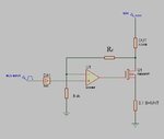
View attachment abc.bmp

This is the setup that I want to use.
It has 2 Resistance connected
1) DUT ,Which is the device under test -Ranges from 10 Milli Ohms to 10 Kilo Ohms.
2)Other is a Precision Shunt whose value is 0.1 Ohms +- 0.1%.
 

Hi,

The IN- of your OPAMP should go to the top connection of shunt (0.1 Ohm).
Then you can setup current with: Current = U+ / 0.1.

For 1A you should give 0.1V to V+ pin.

Mind that every 1mV offset voltage in OPAMP will cause 10mA of current.

***********
I recommend to use a larger shunt value. Up to 1.0 Ohms. Mind the power dissipation of 1W@ 1Ohm.


Klaus
 

The output of DAC shd have varied from 0 to 6V It is not possible so you will need another opamp in the output of DAC.

never forget Vref = Vcc - Vdac

for example with 0.1 ohm on shunt you will need 0.1V Vref

for that Vcc - Vdac = 0.1 V which is not possible

so choose some more greater value of shunt resistor.

- - - Updated - - -

correction

The output of DAC shd have varied from 0 to 6V It is not possible so you will need another opamp in the output of DAC.

never forget Vref = Vcc - Vdac

for example with 0.1 ohm on DUT you will need 0.1V Vref

for that Vcc - Vdac = 0.1 V which is not possible

so choose some more greater value of DUT resistor.

If you want to avoid Vdac going to 6 v or using another opamp you can put Rf and Rsh like this
now equation for current is

Code:
                               I = Vcc - ( Vdac * (Rf + Rsh) / Rsh) /  R

abc.jpg

The recommended value for Rf and Rsh should be higher than 10 k.
 

Hi,

Venkadesh_M
please review schematic. The schematic don´t show a current source.
As long as R_DUT is unknown (this is what the OP wants to measure) one can not calculate current.

if he puts in a DUT of 0.01 Ohms (or even worse: he shorts DUT connections) the current will go up to 10A with VRef of 0.1V. I don´t think this is what the OP wants.

Maybe i´m wrong, but i think a true current source according to my schematic corrections in post #25 should work.

But in the end it´s on the OP to specify what he wants.


Klaus
 

Hi klausst

To be very clear the DUT resistor is R the known resistor and R shunt is the resistance to be measured.

Regards,
Venkadesh M
 

Hello,
I think some Mis-Communication is there regarding the Application of the circuit.
@Venkadesh_M

Our Situation is ,If I am Measuring a Very Low Voltage at the DUT (Device Under Test[Varing Between 1 Milli Ohms to 1 Ohms on a single scale])

then to mantain a current of 1 Amp on the DUT without Burning the power Supply I have to get a potential difference of 0.001 Volts.
So my the supply has to provide a Current of 1 Amp.
The Precised curret has to be calculated from a KNown Precision resistance (SHUNT[0.1 Ohms +- 0.1% FIXED VALUE])
and using a 4Wire Kelvin Method To measure My DUT as Klaus pointed out.
 

Are you using circuit in #24? what is the range of DAC output??

How do you measuring two voltages with one scale, post your full circuit..
 

I am Using Circuit No 24.
DAC has 8 Bit Resolution.
Actually I am Measuring the Voltages By a 2 Channel ADC that Is sampling the Voltages into the MCU across SHUNT and DUT.
 

Hi,

The Precised curret has to be calculated from a KNown Precision resistance (SHUNT[0.1 Ohms +- 0.1% FIXED VALUE])
you should also measure/feedback VShunt with differential voltmeter (Kelvin style)

Klaus
 

Sure Klaus,That Is exactly the method to be used in determining Current in SHUNT via Kelvin Type Measurment for both Shunt and DUT.
 

Venkadesh
Adc ref is 1.225v
Using differential mode for both channels.
And max value that dac can provide is 5v
As all the logics and at 5v except the main power rail that is 6v.
 

You know what is the formula for current in #24 given circuit?

I = ( Vcc - Vdac ) / R

for reducing current you will increase Vdac, and your max Vdac is 5V

for example
Vcc = 6V
Vdac = 5V (max)
DUT = 0.5 ohm
I = (6 - 5) / 0.5 = 2A

DUT = 0.1 ohm
I = (6 - 5) / 0.1 = 10A

Is it OK for you ?
 

Hello,
I think some Mis-Communication is there regarding the Application of the circuit.
@Venkadesh_M

Our Situation is ,If I am Measuring a Very Low Voltage at the DUT (Device Under Test[Varing Between 1 Milli Ohms to 1 Ohms on a single scale])

then to mantain a current of 1 Amp on the DUT without Burning the power Supply I have to get a potential difference of 0.001 Volts.
So my the supply has to provide a Current of 1 Amp.
The Precised curret has to be calculated from a KNown Precision resistance (SHUNT[0.1 Ohms +- 0.1% FIXED VALUE])
and using a 4Wire Kelvin Method To measure My DUT as Klaus pointed out.

I think there is some misunderstanding about how low resistance measurements are made.

1. you don't need 1A to measure 1mΩ
If you have an 10 bit ADC for 3 decades, you need a 50mV shunt to provide 100mA CC

2. You regulate current on the high side and then the D.U.T. Voltage is on the low side.

3. Use an amplifier with a chopper-stabilized or null-adjusted low-drift high gain OpAmp.

4. You choose a gain of 1,10,100 ,1000 even with 0.1% ratios, Selected from 2bit decoded to 4 analog switches.

5. Then a 1mΩ D.U.T. = 100µV @100mA which is amplified x100 to 10mV , which should be adequate for a 3.3 or 5V ADC to a 10bit resolution.

- Then a 100mΩ D.U.T. = 10mV @100mA which if amplified x100 =1.00 V

6. The resulting design can be run from low voltage and current and D.U.T. Never sees more than 100mW @1Ω.

7. The CC can be run from logic level Mosfets from low Vgs in a closed loop. You only need a binary control to choose 0.1 or 1A if you wish to measure D.U.T. = 100µΩ.


8. You can measure 1µΩ with more DC gain than 1000 and 12bit ADC.
 
  • Like
Reactions: d123

    d123

    Points: 2
    Helpful Answer Positive Rating
@SunnySkyGuy
Thank you for your valuable knowledge on this topic.

1) According to you I can just use a 100mA current to pass into the Circuit and measure the resistance accordingly by using a gain Opamp config with chopper stablized version.

2)The type of Gain that you have specified might make the circuit readings abnormal as the little noise present at the system level would be magnified to a great extent if we need to measure a very low resistance of 0.001Ohm(1Milli ohms) [x1000]

3)I will need to use a Zero Drift Opamp for my purpose then,So I have "LTC1051 - Dual/Quad Precision Zero-Drift Operational Amplifiers With Internal Capacitors" as a choice for the above DC GAin Control,I think it looks promising
for our application.

4)What Type of MOSFET Based CC Topology I need to pick up.Kindly show a Rough Sketch for the same .
 
Last edited:

@Venkadesh
I ment the chopper stabilized DC Gain Opamp placed at the DUT Terminals that is used to sense the Voltage and Magnify it via a High Gain OPamp with Low Drift.
 

Status
Not open for further replies.

Similar threads

Part and Inventory Search

Welcome to EDABoard.com

Sponsor

Back
Top