Continue to Site

Welcome to EDAboard.com

Welcome to our site! EDAboard.com is an international Electronics Discussion Forum focused on EDA software, circuits, schematics, books, theory, papers, asic, pld, 8051, DSP, Network, RF, Analog Design, PCB, Service Manuals... and a whole lot more! To participate you need to register. Registration is free. Click here to register now.

Issues with TPS2811 MOSFET Driver for IRF530 in Buck SMPS Design

Status
Not open for further replies.
Hi,

We give informations on partnumbers. Look at at least one of the datasheets found via the linear selection guide.

Please read it - or at least look at the pictures - then you will find out, that there is no need for external drivers nor external FETs. All inside.

As i wrote: 8 parts in total.
How can I say it more clearly? No need to generate a PWM. PWM controller with regulation loop inside. Constant 5V output voltage.

Klaus

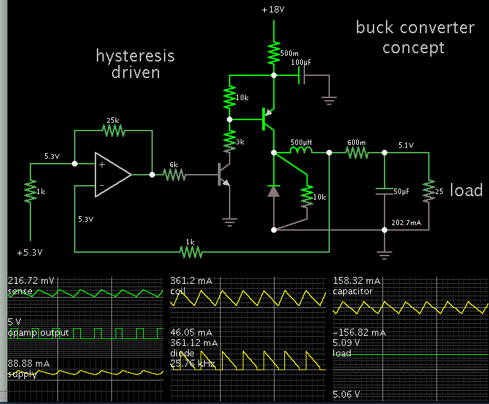
The point me building this smps is that it has to be custom. I can't buy an ic that does the entire buck portion as it wouldn't be custom. Thanks for the input though!
 

Any ideas for selecting an gate driver and would using a pwm controller ic work? Like will it keep the out of my buck converter 5v dc and adjust the duty cycle to keep it that consistent output.
 

A PWM IC designed to drive a P fet, or a normal output one with some transistors to level shift the drive to a P fet will give you a working solution, better to keep the freq to 150-200kHz for efficiency and choice of buck inductors.
Even a low cost CMOS 555 timer can be configured to do this.
 

Is there any ic on the market that will do the pwm with feedback capability? Like it will adjust the duty cycle of the pwm to keep the output at a constant 5v dc?
 

To assist progress, here is a simulation which demonstrates how to drive a buck converter using hysteresis. An op amp is used as a comparator.

Apply 5.2V reference to one input. The output voltage is applied to the other input. (The current-sense resistor is not essential, however it makes for tighter regulation of output voltage.)


The op amp biases an NPN, which in turn biases a PNP. The op amp operates from a 5V supply (which can be provided by a zener diode and resistor combination).

The load can be changed, although it may require adjusting a few other values.
 

Status
Not open for further replies.

Similar threads

Part and Inventory Search

Welcome to EDABoard.com

Sponsor

Back
Top