Continue to Site

Welcome to EDAboard.com

Welcome to our site! EDAboard.com is an international Electronics Discussion Forum focused on EDA software, circuits, schematics, books, theory, papers, asic, pld, 8051, DSP, Network, RF, Analog Design, PCB, Service Manuals... and a whole lot more! To participate you need to register. Registration is free. Click here to register now.

Is this mixer a double balanced mixer?

neazoi

Advanced Member level 6
Joined
Jan 5, 2008
Messages
4,157
Helped
13
Reputation
26
Reaction score
15
Trophy points
1,318
Location
Greece
Activity points
37,198
Is this switching mixer considered a double balanced mixer?
The local oscillator in my case is very low, 3KHz and the RF input is 10MHz.

My goal is, the output of the mixer, not to contain the actual RF input signal (10MHz), but only the rest products of mixing.

Please advise me if this is the case with this mixer.
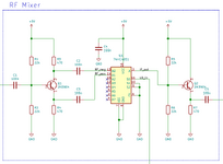
 

Attachments

  • mixer.png
    mixer.png
    27.3 KB · Views: 68
This is not a real mixer. A tricky way has been used but not worth.
If you wanna use a real Mixer, look at NXP SA/NE series mixers/modulators or equivalents.
 

    neazoi

    Points: 2
    Helpful Answer Positive Rating
This is not a real mixer. A tricky way has been used but not worth.
If you wanna use a real Mixer, look at NXP SA/NE series mixers/modulators or equivalents.
It is actually a switching mixer (not non-linear), but instead of diodes it used the multiplexer switches.
After all, it is used in numerous SDR projects, and it works.
 
Last edited:
Depends on modulation signal characteristics. Due to AC coupling, the given circuit gives only correct output if the modulation is DC-free.
 

    neazoi

    Points: 2
    Helpful Answer Positive Rating
Depends on modulation signal characteristics. Due to AC coupling, the given circuit gives only correct output if the modulation is DC-free.
Hm...
I would like to shift a 10MHz SSB modulated signal (coming as an input signal from pins 13 and 14) 3KHz up and 3KHz down at the output of the mixer (pin 3).
The local oscillator it a 3KHz square wave, about 50% duty cycle.
Would the output of the mixer, containing the 10MHz signal apart from the mixing products (10+3, 10-3)?

I think it is a single balanced mixer type, because the input signal is split into 0 and 180 degrees and fed balanced to the input.
I am not sure if this will be able to suppress the input signal at the output and pass only the products.
 
You are apparently confusing balanced mixer with quadrature mixer.
For SSB modulation/demodulation, RF and LO must be 90 degree phase shifted.
 

    neazoi

    Points: 2
    Helpful Answer Positive Rating
You are apparently confusing balanced mixer with quadrature mixer.
For SSB modulation/demodulation, RF and LO must be 90 degree phase shifted.
Thanks a lot.
In this case, I do not mind of the image signal appearing at the output of the mixer, so I do not need a quadrature mixer.
I only care about the RF input signal (10MHz) not to appear at the output of the mixer.

With an SRA-6 double balanced mixer, I could use a 3KHz local oscillator to mix the incoming 10MHz signal, and in theory this 10MHz signal should be suppressed at the output of the mixer. I should only have the products of the mixer in that case 10.003MHz and 9.997MHz.

But in the switching mixer in post #1 I am not sure what will happen? Will the 10MHz signal appear at its output?
The circuit I posted, is from that page https://acidbourbon.wordpress.com/2021/04/11/a-74xx-defined-radio/
 
Suggest to check the circuit in a simulation. Basically LO and RF are not appearing at the output except for some residual crosstalk. But also double balanced mixer has some RF and LO residuals.

Consider that you also see +/- 9 kHz, +/- 15 kHz and so on products of square wave harmonics.
 

    neazoi

    Points: 2
    Helpful Answer Positive Rating
This Mux/Demux CMOS chip will produce a suppressed carrier ( maybe 30~40 dB) but the MUX has a digital input threshold so it is not a linear LO. Thus your square wave might give similar results to a biased sine wave. The differential RF is needed to suppress the carrier should have low inverter latency or use 20MHz /2. e.g. https://tinyurl.com/276uvbfg in my simulation.

If you need a linear mixer a Gilbert mixer and other linear mixer types are possible.

--- Updated ---

Gilbert cell ( discrete version ) Due to limitations of Falstad's autoplot of spectrum, I used 300 kHz to show the suppressed carrier for your 3kHz LO

--- Updated ---

As I recall some who lived on a farm in Iraq (?) made an eloquent SSB using PLL's.
 
Last edited:
This Mux/Demux CMOS chip will produce a suppressed carrier ( maybe 30~40 dB) but the MUX has a digital input threshold so it is not a linear LO. Thus your square wave might give similar results to a biased sine wave. The differential RF is needed to suppress the carrier should have low inverter latency or use 20MHz /2. e.g. https://tinyurl.com/276uvbfg in my simulation.

But isn't SSB a linear signal? So a linear mixer is needed such as Gilbert mixers and other linear mixer types.
--- Updated ---

Gilbert cell ( discrete version ) Due to limitations of Falstad's autoplot of spectrum, I used 300 kHz to show the suppressed carrier for your 3kHz LO

The output spectrum is much cleaner with the gilbert cell mixer!
You have almost convinced me to use this one instead. Eg an old SA612AN

There is a thing that is not clear to me in the gilbert cell mixer though:
Do I need to feed the input 10MHz signal in a balanced configuration, in order for the nulling of this signal to occur at the output of the mixer?

In your simulation you feed it non-balanced.
 
It is balanced 10MHz from the D-FF divide by 2 and symmetrical complementary outputs.

I mean about the gilbert cell mixer (see the example attached).
See figure 4.
Will the direct untuned input in Fig 4a still be able to use the mixer as a double balanced one? Or does it require Figure 4b configuration in order to behave as a double balanced one?
 

Attachments

  • 602.pdf
    915.9 KB · Views: 30
Balanced complementary RF inputs on pins 1&2 means both matching of amplitudes and matching opposite phase which determines the dB of carrier suppression .

So E looks to be the best of these types..
 
Balanced complementary RF inputs on pins 1&2 means both matching of amplitudes and matching opposite phase which determines the dB of carrier suppression and imbalance of USB and LSB.

So E looks to be the best of these types..
So in order for this NE602 chip to work as a balanced mixer (and thus suppressing the input signal at its output) the input signal at the pins 1 and 2 must be of equal amplitude on each pin (1 and 2) and at 180 degrees difference between them.
Do I get this right?
 
I said it wrong. It's just using the differential amplifier suppresses common mode noise such as signals sharing noise from the supply or ground.
So it does NOT require a balanced input at pins 1 and 2 in order to be used as a balanced mixer? Right?
It is not clear to me from the article I attached.
 
Due to the simple SA 602 input configuration, RF suppresion will be probably better with true differential input.
To get the advantage of a linear mixer, 3 kHz LO signal must be sine rather than square wave. Otherwise there's no adavantage over CMOS switch solution.
 
Due to the simple SA 602 input configuration, RF suppresion will be probably better with true differential input.
To get the advantage of a linear mixer, 3 kHz LO signal must be sine rather than square wave. Otherwise there's no adavantage over CMOS switch solution.
Thank you.
Yes, I intend to make a 3KHz sinewave oscillator around the oscillator transistor of the SA602.

>>>...RF suppression will be probably better with true differential input.

However, there will still be a good amount of suppression even in the single-ended input, wouldn't it be?
I mean the mixer will still operate as a balanced mixer internally, no matter if we feed it single ended.

Am I right on this? (I could always try, but your experience is useful)

- UPDATE -
I think this video explains that it does suppress the RF input
In the video case, the uses an audio sine to do up conversion. The RF input is suppressed., even though he drives it single-ended.
 
Last edited:
why don't you use my simulator, the CC sink and matched components may be idealistic and show true differential linearity even with a single-ended input.

--- Updated ---

The unbalanced effects, I suspect will only affect LO leakage which is easy to filter out at 3kHz (and CMRR as I said before) so any of those can be tried with sine wave sources.

The better you simulate interference, noise and balance tolerances, the better the simulation is.
 
Last edited:
Is this switching mixer considered a double balanced mixer?
The answer to your first question is: this is a single-balanced mixer, not a double balanced mixer.
A single-balanced mixer is a step forward from a single-device mixer, which use a single diode or a single transistor.
A single-balanced mixer provides isolation between LO and RF ports, when a single-device mixer cannot provide this isolation.
A single-balanced mixer requires at least two switching components. Two diodes or two transistors. In your case, two switches inside of the 4051 chip.
 

LaTeX Commands Quick-Menu:

Part and Inventory Search

Welcome to EDABoard.com

Sponsor

Back
Top