Continue to Site

Welcome to EDAboard.com

Welcome to our site! EDAboard.com is an international Electronics Discussion Forum focused on EDA software, circuits, schematics, books, theory, papers, asic, pld, 8051, DSP, Network, RF, Analog Design, PCB, Service Manuals... and a whole lot more! To participate you need to register. Registration is free. Click here to register now.

IRF3205 burning at only 25 Amper

Status
Not open for further replies.
Re: help! IRF3205 burning at only 25 Amper

It is far better to use a snubber, and/or gate drive adjustment to limit the dv/dt.

There is an excellent app note on TI's website to calculate snubbers. Do a google search.

Tranzorb devices, in my experience, are very capable with high energy pulses, but not with repetitive ones.

- - - Updated - - -

I was looking again at the schematic you had provided earlier...It is a little fuzzy, but are the gate resistors really 100K???
 
Re: help! IRF3205 burning at only 25 Amper

the component values are not real
I used the schematic only for designing the PCB ( autorouting etc. )

the gate resistors are actually 22 Ohm with a paralel 1N4148 pointing to the IR2113
I think the 1N4148 is for fast turning OFF of MOSFET ( I copied it from an aplication note )
is it a good idea ?

what values do you advice to me instead of 22 Ohm and the diode ?
thank you
 

Re: help! IRF3205 burning at only 25 Amper

...the IR3205 according to datasheet can withstand 55 V and 110 ampers
but in my circuit I limit the current to 25 amperes ...

This is not true, if you are referring to device being simultaneously exposed to that conditions.
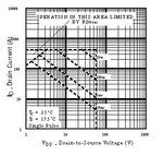
According to SOA figure on datasheet, 25A could be applied to this MOSFET for a PWM period not exceeding about ~0,5 ms.

SOA.JPG

+++
 

Re: help! IRF3205 burning at only 25 Amper

One important thing is the power rating of IRF3205. Its 200W. But your system is 24V and passing 25A. So what is the power? 24X25=600W ???? Then MOSFET will definitely burn.
 

Re: help! IRF3205 burning at only 25 Amper

This is for, to operate in linear region. It does not imply here.

It´s not true.
Note that figure presented above, shows featured characteristics of the device ranging from DC up increasingly switching frequencies.


+++
 

Re: help! IRF3205 burning at only 25 Amper

Current limitation should provide pulse by pulse protection. If current is averaged, there is a risk of excessive current passing. At 20% duty cycle, average current may be 25A but instantaneous current will be 5 times. That is 125 Amps. At lower PWM duty cycle, it can rise further.

One important thing is the power rating of IRF3205. Its 200W. But your system is 24V and passing 25A.
When device is "hard on" voltage reaches near zero, only developed due to Rds_on. 25A passing through 8m_ohm will dissipate only 5 Watts. Voltage developed is only 0.2V
It´s not true.
Similar is the case in the graph where switch is not fully turned on and voltage are present on drain/source.
During hard switch _on, voltage on drain/source is dropped and now applied to the load.
 

Re: help! IRF3205 burning at only 25 Amper

It is highly recommended that you use RC snubber circuit to limit the dv/dt. You can use schottky diodes for fast turning OFF of mosfets.
 

H_mos.JPG
L_mos.JPG

hello dear all , thank you for answers

I cant use snubber - I have very small place
I have attached High mosfets VDS and VGS( upper photo) + Low mosfets VDS and VGS
( VDS blue - VGS yellow line )
I think there is an avalanche problem ( at turning OFF point )- I will remove Gate to IR2113 diode
what else do you advice me ?

also at the Low side there is a false triggering of Low gate - is it dangerous ? how can I remove it ?
 

I cant use snubber - I have very small place...
what else do you advice me ?

I would say that considering employed switching frequency, it is not merely a recommended proceedings, but also almost mandatory.
Sometimes I faced to the same arrangement issue, but always could find a solution.


+++
 

In a regular H-bridge, highside Vds is equal to Vbus - lowside Vds and can't have different voltage swíng. In so far, the waveforms in post #29 aren't plausible.

It's also hard to determine if we see actual false triggering or just measurement artefacts.
 
Status
Not open for further replies.

Similar threads

Part and Inventory Search

Welcome to EDABoard.com

Sponsor

Back
Top