Continue to Site

Welcome to EDAboard.com

Welcome to our site! EDAboard.com is an international Electronics Discussion Forum focused on EDA software, circuits, schematics, books, theory, papers, asic, pld, 8051, DSP, Network, RF, Analog Design, PCB, Service Manuals... and a whole lot more! To participate you need to register. Registration is free. Click here to register now.

Input matching of class C amplifier

froten_103

Newbie
Newbie level 2
Joined
Jun 3, 2024
Messages
2
Helped
0
Reputation
0
Reaction score
0
Trophy points
1
Activity points
25
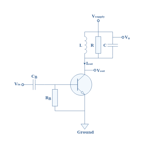
I have constructed the circuit shown in the figure which is class C amplifier for 27MHz transmitter, and is working as expected.

Now I’m trying to match the amplifier to the driving stage which has 50 Ohm output impedance, but I don’t know the input impedance of my amplifier to design the matching network, I need help on how to measure or calculate or estimate the input impedance of the class C amplifier? I just need an approximate value, or a simple method to measure, even a rule of thump is adequate.


Thanks in advance for any help

1717449100728.png
 
The aim of impedance matching is to maximize power throughput. Your amplifier puts out a certain volt level and Ampere level. Together these produce a certain power level (V x A =Watts). And this is suitable for a certain ohm load.

However that same combination of volts and amps may not be the most useful combination for your 50 ohm load. It may not result in maximum Watts.

So you want to build a network (usually made from inductors & capacitors) with values which convert your initial combination of volts & amps into a different combination of volts & amps.

Only if you're lucky does the 50 ohm load already match the impedance, namely by maximizing power throughput. Or possibly you can revise your amplifier's L & C values while operating at your frequency of interest, so as to maximize power throughput to your 50 ohm load.

Thanks for trying to answer my question.

I have no problem matching the amplifier output to the load, the help I need is to match the amplifier input to the signal source (the signal source has 50 Ohm output impedance), I just need a way to get an approximate value of class C amplifier input impedance, or a simple method to measure it, or even a rule of thump is adequate.
 
It strikes me that matching the output impedance will also maximize the distortion. To properly realize any design, you must choose the desired outcome with specs. Being non-linear, the link I posted suggests various applications with different topologies but matched impedance wasn't any of them. For example, selective harmonic output filters require a Q >>1.

Examine the equation using Vi and Icm.

1717499590042.png

View attachment 1717499712134.png
 
Last edited:

LaTeX Commands Quick-Menu:

Similar threads

Part and Inventory Search

Welcome to EDABoard.com

Sponsor

Back
Top