Continue to Site

Welcome to EDAboard.com

Welcome to our site! EDAboard.com is an international Electronics Discussion Forum focused on EDA software, circuits, schematics, books, theory, papers, asic, pld, 8051, DSP, Network, RF, Analog Design, PCB, Service Manuals... and a whole lot more! To participate you need to register. Registration is free. Click here to register now.

Increasing the current handling capability of linear voltage regulators

Status
Not open for further replies.

khatus

Member level 3
Member level 3
Joined
Oct 7, 2017
Messages
63
Helped
1
Reputation
2
Reaction score
0
Trophy points
1,286
Activity points
1,737
Hello guys, I want to calculate the value of resistor R1 in the figure. But while doing the calculation I face the following problem
First, see the pictures below,

lm340-page-016.jpg


In my calculation, VBE =0.7 = I1* R1 to turn the transistor on. But here, but Here I1 = IREG was taken, so that
R1 * IREG = 0.7 volts.
I did not understand this part, In my calculation,

Input-current_question.PNG


At the junction,

I1+IB = IREG

IREG - IB = I1

Now the Beta of the transistor is known and From the output current I can calculate IC and I can find IB from IC.
a) So I1 and IREG are not the same. So how did equal this two here?
b) Where can I find the maximum value of IREG?
c) To calculate the output current I need at least two quantities from ( I1, IB, IREG). How i can determine these two quantities
 
Last edited:

Hi,

Forgive me if I am wrong. But I doubt that the curve says the efficiency is around 20%

24V input, 5V output, let´s say 1A load current, and 8mA GND_leg current.
Pi = 24V x (1A + 8mA) = 24.192W
Po = 5V x 1A = 5W

eff = (Po / Pi) * 100 % = 5W / 24.192W * 100 % = 20.67%

O.T.:
Obviously efficiency cannot be greater than one
There are plenty of youtube videos that contradict this.
But all these inventions are stolen by corrupt governments.
;-)

Klaus
 

It comes from some logs. I mean logarithms. (it was introduced as a torture device for young students).

That is incorrect. No logs were used in the sim. It has to do with where I place
the current probe, entrance or exit of the device being probed.

Forgive me if I am wrong. But I doubt that the curve says the efficiency is around 20%

Wrong....

Efficiency of a 3 terminal regulator -

1665517487195.png


Regards, Dana.
 
That is incorrect. No logs were used in the sim. It has to do with where I place
the current probe, entrance or exit of the device being probed.


Wrong....

Efficiency of a 3 terminal regulator -

View attachment 179056


Regards, Dana.
Thanks for the clarifications.

Perhaps I am watching too many YouTube videos!!
 

Hi,

The BD540 is a power transistor so we should expect it to have a low beta. In fact, its data sheet values confirms this. so, the base current should not be neglected.

I'd recommend you use the minimum value of beta as given in the datasheet.
Iout(worst case) = Ib*(beta + 1) + IR1
So if we let Ib to be one-tenth of IR1, we have: Iout(worst case) = 0.1*IR1*(beta + 1) + IR1
So that Iout(worst case) = IR1*(1.1 + 0.1*beta)
Therefore,
IR1 = Iout(worst case) / (1.1 + 0.1*beta)
R1 = Vbe/(IR1)

If you are still concerned with the regulator's Icc, then you can include it in the equation as follows:
Iout(worst case) = Ic + Ib + IR1 - Icc
so that Iout(worst case) + Icc = Ic + Ib + IR1 = IR1*(1.1 + 0.1*beta) -- where I have used Ib = 0.1*IR1.
Therefore,
IR1 = (Iout(worst case) + Icc) / (1.1 + 0.1*beta)
R1 = Vbe/(IR1)
 

Be careful with output C ESR, here I set it at 0 ohms, so regulator loop went into
oscillation. Raising the ESR (R3) to 1 ohm killed the oscillation. So choose C wisely.

1665708578689.png


Regards, Dana.
 

lm340-page-016 - Copy.jpg


I want to know how the above equation arrives.I Have tried but I can't make it
two_transistor-network - Copy.PNG
 

For transistor Q2,

VBE(Q2) = 0.8 = ISC × RSC

From output side of the regulator we get,

ILOAD = IREG + IC1

From input side of the regulator we get,

IREG = IB1 +IC2 +IR1

IB2 =( β+1)× IE2
 

Hi,

I guess the whole circuit does not work satisfactory, .. it relies on the current limiter inside the 7805.
It may work, but it´s not the best soultion.

How it works:
Increasing load current through U1 and R1 causes an increasing voltage drop across R1.
This voltage drop causes to increase_V_BE of Q1.
At about 0.55V (up to 0.8V) Q1 becomes conductive providing increasing additional current to the load.

At rising load current the current through RSC rises. --> increasing V_BE of Q2. Q2 becomes conductive and limits the current through Q1.

The "0.8V" is the expected V_BE of Q2 at full current.

The problem:
As soon as Q1 current is limited ... now U1 tries to maintain output voltage by increasing it´s current ... until internal limit.

Klaus
 

For transistor Q2,

VBE(Q2) = 0.8 = ISC × RSC

From output side of the regulator we get,

ILOAD = IREG + IC1

From input side of the regulator we get,

IREG = IB1 +IC2 +IR1

IB2 =( β+1)× IE2
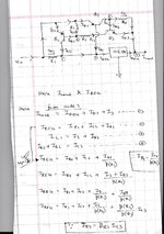
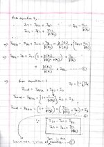
I have derived the equation as shown in the attachments below. In the equation for R1, everything after the division sign is the denominator. You can substitute ILOAD(max) and IREG(max) for ILOAD and IREG, respectively.

I have used different beta variables for the transistors. They used the same beta variable for both transistors. You can replace both beta(Q1) and beta(Q2) in mine by beta to reflect their expression.

Notice the extra term with IC2 in my equation? If IC2 is set to zero, then both equations for R1 are identical. So, it means that their equation is for achieving ILOAD(max) with IREG(max) prior to Q2 turning ON. In my equation, you can set it to zero or choose an appropriate different value for it.

Also, I have gone ahead to derive an expression for RSC based on ILoad and IREG.
 

Attachments

  • Page 1.jpg
    9.9 MB · Views: 118
  • Page 2.jpg
    9.3 MB · Views: 115

Page_00363.jpg


Here is another example of an Outboard Current Boost Circuit. I am trying to find out the values of Rsc and R1 and R2.
But did not succeed. Can anybody remove the term IR1 in equation 5 so that only IREG, ILOAD, and IC2 remain in the equation??
In case if my solution is wrong then please solve this equation and find the values of Rsc, R1, R2, and R3 for me.

outboard_transistor_booster_1.jpg

outboard_transistor_booster_2.jpg
--- Updated ---

Hi,

Do you see the Darlington between Input and Output?
yes
 
Last edited by a moderator:

Here is another example of an Outboard Current Boost Circuit. I am trying to find out the values of Rsc and R1 and R2.
But did not succeed. Can anybody remove the term IR1 in equation 5 so that only IREG, ILOAD, and IC2 remain in the equation??
In case if my solution is wrong then please solve this equation and find the values of Rsc, R1, R2, and R3 for me.

View attachment 179241
I will look at what you have done in detail later on. However, I think I caught something. The expression you showed in a box on the last line of your first page is not what it should be. The relationship is IC3 = beta(Q3)*IB3. I'd encourage you start from there to review your work and then let us see what you have come up with. If there's another catch, we will let you know.

I believe it will be helpful to you if we take that path to get you to pick up the expressions you are missing in the derivation process.
Hello, Akanimo I cam not solve it. Can you solve it for me?
 

Hello, Akanimo I cam not solve it. Can you solve it for me?
Here is what I have done.

I am numbering every equation so you could easily ask questions if you have to. Please take a little bit of care with the nodes that you numbered. The equations for the nodes are numbered differently in my solution.
 

Attachments

  • Page 1.jpg
    10.6 MB · Views: 107
  • Page 2.jpg
    10.8 MB · Views: 98
  • Page 3.jpg
    10.3 MB · Views: 100
Status
Not open for further replies.

Part and Inventory Search

Welcome to EDABoard.com

Sponsor

Back
Top