Continue to Site

Welcome to EDAboard.com

Welcome to our site! EDAboard.com is an international Electronics Discussion Forum focused on EDA software, circuits, schematics, books, theory, papers, asic, pld, 8051, DSP, Network, RF, Analog Design, PCB, Service Manuals... and a whole lot more! To participate you need to register. Registration is free. Click here to register now.

Increasing OpAmp output current

engr_joni_ee

Advanced Member level 3
Joined
Nov 3, 2018
Messages
822
Helped
2
Reputation
4
Reaction score
7
Trophy points
18
Activity points
6,877
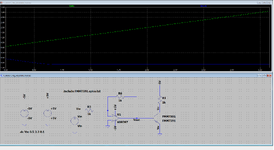
The input to the OpAmp is 0 to 3.3 V. I am using OpAmp in unity gain inverting configuration. The output of the OpAmp will be 0 to -3.3 V. The problem is that the output current of the OpAmp I have selected can not deliver 500 mA if a load is connected. I know that there are OpAmp with higher output current but for some reason, I need to find a solution with FMMT591 OpAmp. One option is to buffer the output using a transistor to increase the output current. I am using PNP at the output of OpAmp. The schematic is attached. Kindly have a look and suggest how can I get 0 to -3.3 V at the load that require 500 mA. Note that the input of the OpAmp will be controlled by DAC/FPGA to get adjustable power supply at the load.
 

Attachments

  • Untitled 738.png
    Untitled 738.png
    48.1 KB · Views: 156
Last edited:
Addressing #19.

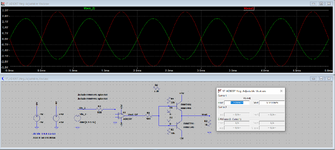
Now I attached R6 to the output point where two emitters come together.
I also change the value of R1 from 1k ohm to 500 ohm. I guess this will increase the base current.
The resistor values R6 and R3 are changed to get 0 to -3.3 V at the Vout. The load is R2.
Two diodes are added to remove cross-over.

I will come to D.A.(Tony)Stewart comments #16 and #20 latter.
 

Attachments

  • Untitled 746.png
    Untitled 746.png
    78.6 KB · Views: 64
1. The circuit can be significantly reduced if the required output is single quadrant (one transistor class B output stage), as previously discussed.
2. As also discussed, FMT591 has insufficient power rating.
 
Also no short limit protection in any of circuits so far....?

And OP back to posting 4 quad solution sim....
 
I also change the value of R1 from 1k ohm to 500 ohm. I guess this will increase the base current.
Why do you "guess"?
You use a simulation tool. You simply can measure the base current ... to validate your expectation.
And to learn from what you see, to understand how a bjt works.

For me speaking: "guessing" is not the way to design elelctronics. Electronics follows physics, mathematics, rules.
Guessing "the voltage is not dangerous", "the BJT will survive", "the airbag in your car will not ignited during normal driving", "the measurement tool will show the correct value" .. is no option. I personally want to be SURE about this all.

Two diodes are added to remove cross-over.
Initially you did a one quadrant solution.
The one quadrant solution does not suffer at all from crossover problem .. there simply is no crossover.

And with the diode solution I expect thermal runaway ... it´s very likely the BJTs get killed.

It´s hard to help. We (at least I) still don´t know your true application requirements.
***

Three years ago Doa wrote: https://www.edaboard.com/threads/microcontroller-with-rs-485.399315/post-1718363
I see no spark, no improvement, no "start"... not even a good communication.

I better leave...

Klaus
 
Two diodes are added to remove crossover. is not needed as I explained.
R6/R3 gain is too low to meet datasheet specs for max Iout. Av = 2 minimum so that Vgs/Vgs(th) > 2 to get low RdsOn. as I explained already.

#20 demonstrates 6x your 500 mA output. Is that enough margin? ')
 
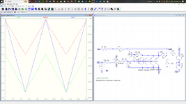
Added pre-biased ~ 1A current limit. Actions outstanding : joni Vout, load specs

1719153389694.png


NFB to Q1 reduces the current limiter to less than 0.6V drop on R7.
R10 improves Vout response near 0V.

1719153639636.png
 

Attachments

  • 1719153597562.png
    1719153597562.png
    197.1 KB · Views: 57
Last edited:
Manufacturers still supply screened beta parts any more, like back in the 60's, 70's ?
I know NSC started walking away from that in the 80's......

Or just use ballasting .......in each individual emitter......
 
Manufacturers still supply screened beta parts any more, like back in the 60's, 70's ?
I know NSC started walking away from that in the 80's......

Or just use ballasting .......in each individual emitter......
Rohm always has some binned parts for discrete hFE.

But that's a good point. The shared PNP with the highest hFE gets the hottest which if not sharing a Cu heatsink can lead to thermal runaway.

My Rule of Thumb is to add some value of <Rce(sat) as a fixed Re value to normalize if expecting it to run hot to reduce Pd by 50% and space enough to reduce temp rise or use Manhatten style THT R's with shortest lead to gnd plane.

e.g. 2N2907 Rce(sat) = 400 mV/ 150 mA = 2.67 Ohms which might cause clipping with 6 Ohm load, so 1 Ohm would help normalize current sharing.

Cheers,

Tony

Winterpeg attachment to remind me to keep cool in 40'C humidex.
 

Attachments

  • 1719157377017.png
    1719157377017.png
    1.1 MB · Views: 57
Last edited:
Turns out thru sim, using 2 Q's, beta 150 and 300, very little change. The emitter degen
seems to take care of it. Plots R1 2 - 6 ohms.

1719158123479.png
 
As expected, Ic depends on Vbe which has a NTC ~ -4mV/'C so actual resistance tolerance is the key to modulating Ic(Vbe) which as shown in SPICE models as RE = 0.1 for 2N3906 and RE= 0.2 for 2N2907 which accounts for the mismatched sharing more than Beta Forward (BF).

So I agree it's not hFE when Vbe is the same but this tolerance on "RE" is not given in SPICE models, so we only have Rce(sat) max. specs which includes "RE".

from LTspice:
.model 2N2907 PNP(IS=1E-14 VAF=120 BF=250 IKF=0.3 XTB=1.5 BR=3 CJC=8E-12 CJE=30E-12 TR=100E-9 TF=400E-12 ITF=1 VTF=2 XTF=3 RB=10 RC=.3 RE=.2 Vceo=40 Icrating=600m mfg=NXP)

.model 2N3906 PNP(IS=1E-14 VAF=100 BF=200 IKF=0.4 XTB=1.5 BR=4 CJC=4.5E-12 CJE=10E-12 RB=20 RC=0.1 RE=0.1 TR=250E-9 TF=350E-12 ITF=1 VTF=2 XTF=3 Vceo=40 Icrating=200m mfg=NXP)

The RE difference value of 0.1 Ohm is significant to current sharing with 500 mA shared effects on internal Vbe. I think RE = rPI/hFE?
 

LaTeX Commands Quick-Menu:

Part and Inventory Search

Welcome to EDABoard.com

Sponsor

Back
Top