Continue to Site

Welcome to EDAboard.com

Welcome to our site! EDAboard.com is an international Electronics Discussion Forum focused on EDA software, circuits, schematics, books, theory, papers, asic, pld, 8051, DSP, Network, RF, Analog Design, PCB, Service Manuals... and a whole lot more! To participate you need to register. Registration is free. Click here to register now.

Implement I2C in VHDL

Status
Not open for further replies.
I tried to edit my last post, but was impossible. Anyway, yes, I do, and I changed the state machine as it should be, just with the states. So...

Code:
PROCESS(ep, es, reset, change)
	BEGIN
		IF(reset='1')then
			es<=e0;
		ELSE
			CASE ep IS
				WHEN e0 =>				--Estado de conf
					es<=e1;
				WHEN e1 =>
					if(change='1')then
						es<=e2;
					end if;
				WHEN e2 =>
					es<=e2;
				WHEN OTHERS =>
					es<=es;
			END CASE;
		END IF;
	END PROCESS;
	espera<='1' when ep=e1 else '0';
	go<='1' when ocupado='0' else '0';
	command<=cmd_config when ep=e0 else cmd_write when ep=e2 else command when ep=e1;
	data<=data_ports when ep=e0 else data_out when ep=e2 else data when ep=e1;

Now I don't manipulate signals on the state machine, just the status.
I assign the signals out of the process, so now I don't get latches on "data" nor "command".
But I have the following problem, latch on "es".
Warning (10631): VHDL Process Statement warning at pruebaI2C.vhd(58): inferring latch(es) for signal or variable "es", which holds its previous value in one or more paths through the process

I don't know why I have a latch in that point. I also tried to remove the "when others" condition, because I'm describing all possible conditions, and to remove "es" from the sensitivity list, but the result is exatly the same.

About your questions, yes, I know the differences between combinational and sequential circuits, but I'm not an electronic engineer, I'm a computer engineer and I often think in software where it isn't. I must change my mind but it's not a thing I can do from today to tomorrow, the process takes it time.
If I'm programming this I2C is because I need to make the protocol work. You've seen in this thread that at first I tried to use IPCores from other people, now I'm doing it by myself, I'm putting effort, I just want to learn and make it work.
 
Last edited:

I tried to edit my last post, but was impossible. Anyway, yes, I do, and I changed the state machine as it should be, just with the states.

That's wrong code for SM. There isn't any clock there.
You need to brush up your RTL coding fundamentals.

- - - Updated - - -

Ok, then you have to first understand how state-machines are coded in RTL. There are 2 styles prevalent in SM coding (2 process approach and single process approach). You might choose one depending on which one you understand the best. My recommendation will be the one process approach.

About your questions, yes, I know the differences between combinational and sequential circuits, but I'm not an electronic engineer, I'm a computer engineer and I often think in software where it isn't. I must change my mind but it's not a thing I can do from today to tomorrow, the process takes it time.
As I mentioned earlier, you could have started with a simple project rather than an I2C, the learning curve will be very steep here.

So if time is a constraint on your side, then I would still say use IP cores.
 
Last edited:

The one-process style always kills me a bit. It is a failing of VHDL/Verilog. From a technical standpoint, 2-process is strictly better. but who cares? The languages aren't designed for HW development.
 

The one-process style always kills me a bit. It is a failing of VHDL/Verilog. From a technical standpoint, 2-process is strictly better.
Single process isn't the problem here, it's not using registered (edge sensitive) logic.

In my view, two process state machine design is mainly a text book legacy. But no problem if you prefer it or are used to it. Beginner attempts published at Edaboard are often asking for help with unintentional latches, which raises my doubts about this implementation style.

I confess that state machines I write from the scratch are always using a single registered process. Combinational logic may supplement it if special behavior of output signals is required.
 
In my view, two process state machine design is mainly a text book legacy.

But is this because having access to next_state/next_value is a bad thing? Or just because one-process is less tedious?

(also, I've seen a fair amount of "why is this delayed" posts from forum users.)
 

As I mentioned earlier, you could have started with a simple project rather than an I2C, the learning curve will be very steep here.

So if time is a constraint on your side, then I would still say use IP cores.

I started with easier projects. I began manipulating the switches, buttons and leds of the development board, later I did it with GPIO and ADC interfaces and now I am working with communication protocols (I2C, SPI and probably also Ethercat).
In my OP I asked about the IP Core, which I don't know how to use, but "I wasn't showing any effort of my own" so I wrote my own code and crossed my fingers to make it work, unfortunately I still have problems as you see on this thread.

Well, I continue with my story. I corrected some mistakes and now there is not warnings nor anything with my code.
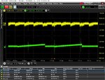
Also, I fixed the protocol, so the clock and the data uses 'Z' (high impedance) and '0' (ground). On ModelSim the simulation seems to be right, but when I program it on my FPGA and put my oscilloscope to analyze the signals, it doesn't works at all.

chronogram.PNG
i2c.jpg
What may I be doing wrong?

Here is the source code updated:
View attachment I2C.zip
 

Hi,

You are in the mV range, close to zero Volts. Are you sure you installed the pullup resistors correctly?

Klaus
 

Hi,

You are in the mV range, close to zero Volts. Are you sure you installed the pullup resistors correctly?

Klaus

No, I'm not sure, in fact I don't understand what are you asking, I'm new to all of this.
I modified the pin voltage to 3.3 if is that what you mean?
If it can help, I am working with Quartus II, but I don't know what you mean with the pull up resistors installation.

pin_planner.PNG

Edit:
I also tried to make another project to test the high impedance output. I did it with a 1Hz square signal and it worked. There I had 1.8V at 'Z' and 0 at GND. So i guess the problem is with the speed, because the same project was modified to 50Mhz and it didn't work.

Edit 2:
I see in the pin planner is a field called "reserved". I guess you are talking about that, but I don't know how should I complete it.

Edit 3:
I changed the reserved field of SDA an SCL to "As output driving Vcc" and now I get these warnings:
Warning (169133): Can't reserve pin SCL -- pin name is an illegal or unsupported format
Warning (169140): Reserve pin assignment ignored because of existing pin with name "SCL"
Warning (169133): Can't reserve pin SDA -- pin name is an illegal or unsupported format
Warning (169140): Reserve pin assignment ignored because of existing pin with name "SDA"
The Board is a Terasic DE10-Nano.
 
Last edited:

Hi,

external resistors are mandatory! - you really should read some I2C specification.
They are real resistors and need to be connected / soldered as pullup rsistors at SCL and SDA. They have nothing to do with HDL, Quartus or anything else..

Klaus
 

Hi,

external resistors are mandatory! - you really should read some I2C specification.
They are real resistors and need to be connected / soldered as pullup rsistors at SCL and SDA. They have nothing to do with HDL, Quartus or anything else..

Klaus

I insist, I'm not an electronic engineer, I only have some notions I learned by myself.
I don't know how is the circuit to make a pull-up resistor nor how? Could you facilitate me a scheme or something?

Thx in advance.

Edit:
I don't know if I'm getting it, but...
What you suggest is connect the SCL and SDA wires to 3.3V with a 10k resistor individually?
 
Last edited:

Hi,

I don't know how is the circuit to make a pull-up resistor nor how? Could you facilitate me a scheme or something?
Every basic I2C specification shows this. Every basic I2C turorial shows this.
A forum can´t replace reading specifications on your own.

I don´t feel responsible for this problems. I surely won´t visit you to (show you how to) solder two resistors.
There should be people in your company able to do this for you. It really is basic stuff.
You try to implement I2C in HDL, thus I expect you know what a pullup resistor is. No need to be an electronics engineer to understand this.

Klaus
 

I guess is something like this?
i2c-pullups.png
Ignore the Arduino picture, I have just created it on Tinkercad.

I know how to solder and read layouts/schematics, that's what I was asking for. I just have doubts because I see different circuits on google and I don't know which one should I follow.
 

Hi,

Don´t use random Google schematics, use reliable sources --> read specifications. That´s why they are made. They are free available in the internet.

Additionally a google search for "I2C pullup" gives about 1 million hits. I assume at least 90% will solve your problem.

Btw:
Maybe you expect me to tell you the values... --> I can´t tell you what value to choose, because I don´t know your system requirements.
Thus I can only repeat: Read the I2C specification, it tells you how. (You may find it boring, but any of us needs to do it. Either me or you ... I recommend "you")
Additionally there are a lot of internet resources on how to do this. (They all should do it according the I2C specification.)

Klaus
 

After putting the pull-up resistors the signal on the oscilloscope is good, but the ACK bit is '1', so the device is not responding.
I have been analyzing my code, but I still don't find any solution. The simulation is right and the signal I am obtaining in the real world is right, then, why is not the peripheral working correctly?
Thx for your responses, they were helpfull.
 

Please show oscilloscope waveforms that includes start condition, address byte, expected acknowledge. Even in the simulation waveforms there's no complete record yet.
 

Please show oscilloscope waveforms that includes start condition, address byte, expected acknowledge. Even in the simulation waveforms there's no complete record yet.

First of all, thanks for your interest. I think I finally have found the mistake.
Yesterday I connected an USB logic analyzer. The software knows the protocol I2C, so I tried with it.
On the chronogram I observed that there were only start and stop signals, so when I try to send the first bit ('1'), it recognizes the rising edge as stop signal. So the problem will be probably related to timings.
Today I will try to correct it and I hope to make it work, maybe I'm being too optimistic.
 

You got a latch BECAUSE of your "when others" statement (and perhaps other reasons, too). This is explicitly saying: 'latch the present value if no other condition is true'. If you actually WANT a latch, this is not a problem.
 

The one-process style always kills me a bit. It is a failing of VHDL/Verilog. From a technical standpoint, 2-process is strictly better. but who cares? The languages aren't designed for HW development.

Early synthesis tools weren't capable of separating out registers from combinatorial logic, which is why designers used the 2-process approach, one process for registers and another for logic. Tools are much more capable now and more (most) people favour the one process approach. Also, the 2-process approach has some disadvantages. It's error prone when making sensitivity list updates and cumbersome having twice as many signal names.
 
The one-process style always kills me a bit. It is a failing of VHDL/Verilog. From a technical standpoint, 2-process is strictly better. but who cares? The languages aren't designed for HW development.

There is nothing intrinsically better in the 2-process style. Why is the one process a failing?? And "aren't designed for HW development"?? That's EXACTLY what they were designed for; the H in HDL stands for hardware.
 
Status
Not open for further replies.

Part and Inventory Search

Welcome to EDABoard.com

Sponsor

Back
Top