Continue to Site

Welcome to EDAboard.com

Welcome to our site! EDAboard.com is an international Electronics Discussion Forum focused on EDA software, circuits, schematics, books, theory, papers, asic, pld, 8051, DSP, Network, RF, Analog Design, PCB, Service Manuals... and a whole lot more! To participate you need to register. Registration is free. Click here to register now.

Impedence Matching for RF circuit at 953MHz

Status
Not open for further replies.

shaikss

Full Member level 4
Joined
Jun 18, 2007
Messages
229
Helped
1
Reputation
2
Reaction score
1
Trophy points
1,298
Activity points
3,319
Hello Folks,

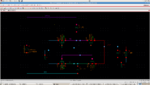
I am designing a rectifier circuit using Cadence 180nm technology.
I am using a sine source which acts as antenna voltage. I have given the amplitude as 1.02V.
Without any impedance matching, I connected the antenna source to the rectifier circuit along with 10kohm load resistance.
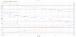
I measured the impedance of the rectifier. I had attached the plot.

Now, the question is , How can I realize that impedence into a R-C parallel combination network?
The next question is, How can I do impedance matching?

Please suggest something.
 

Attachments

  • imp_1.02.png
    imp_1.02.png
    25.7 KB · Views: 95
  • circuit.png
    circuit.png
    75.2 KB · Views: 101

well I you are trying to match the antenna to the circuit, you do NOT want to use and resistors! That would simply make the match better by absorbing the rf power. U need to use capacitors, inductors, transmission lines, or transformers.
 

I guess you determined the impedance in AC analysis? If so, the results won't be correct. It's a non-linear circuit that must be analyzed in transient analysis (or with harmonic balancing, if available).

The present simulation shows a pure capacitive impedance (not admittance as suggested by the letter Y), which is plausible with MOSFET completely switched off.

Yes, I measured it in AC analysis. I measured it in Transient analysis.
What do you suggest me? I want to realize the parallel combination of R and C network for a rectifier.
I need a matching network for maximum power transfer. How should I take this forward? I am simulating at 953MHz.
 

Status
Not open for further replies.

Similar threads

Part and Inventory Search

Welcome to EDABoard.com

Sponsor

Back
Top