adnan_merter
Full Member level 3

- Joined
- Jan 23, 2008
- Messages
- 160
- Helped
- 6
- Reputation
- 12
- Reaction score
- 6
- Trophy points
- 1,298
- Location
- The most beautiful city of the world
- Activity points
- 2,526
The observations are described rather vague.
- how is the DC bus supplied (e.g. rectifier bridge, lab supply)
- what's the bus capacitor value
- what's the load value
- which modulation is used in test
- what's the kind of change (voltage drop, voltage rise, ripple, high frequency transients) and it's magnitude
-dc bus is la lab supply
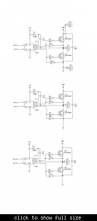
-i connected 100nf capasitor to each pair of igbts ,as can be seen from figure
-i didnt attach a motor but i connected 100 ohm resistor to each output,(i am considering if -the real motor changes something)
-i used pwm by mc3phac by motorola corp.
-the change occours as voltage drops during the switching
i hope they are clear enough


