Continue to Site

Welcome to EDAboard.com

Welcome to our site! EDAboard.com is an international Electronics Discussion Forum focused on EDA software, circuits, schematics, books, theory, papers, asic, pld, 8051, DSP, Network, RF, Analog Design, PCB, Service Manuals... and a whole lot more! To participate you need to register. Registration is free. Click here to register now.

IGBT always boom during load testing!

Status
Not open for further replies.
Was hoping you might show us the actual circuit to help in finding the faults in your design....?

Actually the UC3706 is a pretty poor choice of transformer driver given its high V drop when driving and holding low, you need a discrete circuit or a driver with a mosfet o/p stage to get a really low impedance drive (@ VHF) to the GD Tx, else you will get dV/dT induced turn on in the "other" device which will cause shoot thru losses, lots of RFI and overheating....!
 
here Anna Conda
UC3706.jpg
the T2 is the same transformer with my previous image about MOSFET circuit.
 

The converter operating frequency seems too high. At this high operating frequency you may end up shorting each leg of the converter while transitioning between switches.
Look at the switching characteristics of the IGBT in the datasheet.

Turn on delay time - 76 to 99 ns
Turn off delay time - 332 to 365 ns

You need to have at least 0.5 - 0.6 us dead time in the circuit.
 

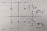
here's the updated IGBT circuitry for the IGBT.
IGBT schematic.jpg
I have measure my gate to emitter using o'scope and the frequency measured is 50kHz for both. PWM frequency is around 101kHz also. see pics below
oscope igbt1.jpg
oscope igbt2.jpg
compared to the theoretical calculation:
PWM UC3524, F=1.18/RtCt
Rt=866 Ohms
Ct=0.01uF
therefore F=136.26kHz
 

I can't believe that you consider 60V pulses of 150 or 200 ns width as regular gate signals. I would expect +/-12 to +/- 15V square waves.

In addition, what's the RCD circuit good for? Must be expected to decrease dead time.
 

The discharge of the .047 relies on the current flowing back down the transformer secondary via the limiting resistor. So the impedance of the transformer and that of the driver output impedance is crucial . If its not low, the capacitor will discharge slowly , hence causing the negative edge of the pulse to extend. You are using the UC3706 in totem pole mode and not single ended?.
Frank
 

Dear FvM, I am not aware of triggering gates with dual voltages w.r.t ground. Is there any such method used for IGBT gate triggering?
With high power IGBTs, bipolar gate drive is standard. It's not necessarily required for small IGBTs and unusual for MOSFETs.

But apart from being required or usual, the output of a gate transformer without additional level shift circuits will be bipolar in any case, because the average output of a transformer is zero.
 

it's single ended input, totem pole output

The discharge of the .047 relies on the current flowing back down the transformer secondary via the limiting resistor. So the impedance of the transformer and that of the driver output impedance is crucial . If its not low, the capacitor will discharge slowly , hence causing the negative edge of the pulse to extend. You are using the UC3706 in totem pole mode and not single ended?.
Frank

- - - Updated - - -

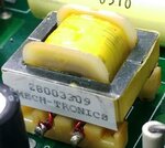
I did not check my transformer with the scope. Im not sure if it's a 1:1 tx. it is small 28003309 from Mech-tronics
You also need a tightly coupled gate drive transformer, do you have a pic of the one you are using?
 
Last edited:

How about posting a link to the data sheet for the Tx? it appears it is too small for the freq you are using and not 1:1 given the high output, can you post a complete schematic also...?
 
I don't have the complete schematic Orson. I don't have also the data sheet for the transformer. 28003309 Mech-tronics label is all I have. Any ideas what is this transformer.

Series coupling caps are for steady state volt-second balance and prevent transformer saturation.
 

Well, looks like you need a new gate drive transformer, with enough V.uS rating to do the job...! and good enough coupling too...!
 
I tried to search this Tx but I couldn't get the exact part online
 

Series coupling caps are for steady state volt-second balance and prevent transformer saturation.
There are no "series couling caps" in your schematic, just a RCD load. In any case, preventing saturation on the secondary side sounds like a misconception with primary push-pull drive.

If you don't have transformer specs, you need to measure it yourself, particularly main and leakage inductance and saturation voltage integral. Of course oscillscope measurements can also prove transformer qualification. I'm still puzzling about the waveforms shown in post #25 (actual voltage scaling, referred inverter operating point).
 

Yeah the waveforms you showed before need explaining. Looks like the core is saturating very quickly, or just has an extremely low inductance, which would explain the short pulse shape, and also the primary voltage is being stepped up to extremely high voltages.

Can you show a picture of the gate drive transformer?
 

Status
Not open for further replies.

Similar threads

Part and Inventory Search

Welcome to EDABoard.com

Sponsor

Back
Top