Continue to Site

Welcome to EDAboard.com

Welcome to our site! EDAboard.com is an international Electronics Discussion Forum focused on EDA software, circuits, schematics, books, theory, papers, asic, pld, 8051, DSP, Network, RF, Analog Design, PCB, Service Manuals... and a whole lot more! To participate you need to register. Registration is free. Click here to register now.

I want to build a controllable high voltage power supply

Status
Not open for further replies.
Thanks so much

So what kind of capacitor should I choose you think is better? Since the input is from variac and I guess its frequency is 60Hz.
 

So you want 15 KV. Thats 60 X 240 v, so you would need 60 stages of a CW multiplier, each with a 2 X 240V diodes + 2 X HV capacitors. bearing what I said before in mind, the first stages should be about 60 X the value of the last ones.
One other option would be to use some form of EHT transformer and feed it with a variable low voltage source, but you will have to use a EHT rectifier diode if you want DC. These sort of diodes can be recovered from old cathode ray colour TVs. Quite often they are arranged as a tripler with 8KV pulses going into them and up to 25KV DC coming out at a relatively low current ~4 mA max. A proper iron based EHT transformer is an expensive and rare item. An ignition coil which steps 12V to 20KV is relatively cheap (try a car scrap yard), but would be limited to a low current (~ .5mA?). If this is enough current then this is what I would do :- 1. get a tripler from a scrap TV. 2. get a car ignition coil and wire the tripler to the HV windings 3. Power the 12 winding of the ignition coil from the output of a medium power audio amplifier, say with a 50W output. 4. Feed the audio amplifier with a variable level 2 KHZ square wave. Thats it. What do you chaps make of this?
Frank
 

Its real hard to control a n stages capacitor is n time value of the last ones.But it seems that its only way I can do.

Thanks a lot.
 

Thats just to optimise the losses across the stages. But it would be worth to use the calculated values or larger. Looking at BradtheRad 's figure, the first stage pumps a 230V pulse, the last 30V. So if you loose 10% of the last stage you loose 2.7V from the total. If you loose 10% of the first, you loose 10% of the output voltage, which is 10% X 1090 = 109V. Brad uses .1 MF, whose reactance at 50 HZ is 10^6/2 X PI X 50 X .1 ~30 K. If you look at Brads volt drop from stage to stage, the first stage "looses" about 48V, the last 3.5. He would have done better to use the capacitors from the last three stages or so across the first three stages. Halving the 48V drop on the first stage would give you about 8% more of the output voltage ( 80V) while the last stage only gives 30V increase and you save on less diodes!!.
Frank
 

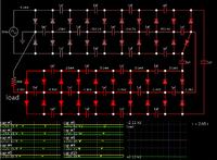
Here is my simulation using 1 uF all round:


Each capacitor develops a greater charge. There is now 2 kV on a 20M load.

Notice that the snapshot was taken at a point where several mA are going through the highest V stages. The current needs to be that high in order to develop higher charges on the caps. (This was not possible in the first simulation when the caps were .1 uF.)

I turned the diodes around so that the output is negative polarity. I suppose that's what you want when doing coronal wind experiments.
 

Same argument, first stage, Vin = 258.7, Vout = 244.8, losses = 9.9 V, = ~10/250 % = 4 % X 2KV = 80V. So doubling the first set of caps will halve this i.e. you will get an extra 40V out. The last set of caps loose 187.7 -186.3 = 1.4 V ~ 1.4/186 = .7%, so making this set of caps smaller will hardly effect the output voltage. i.e. halving them to .5MF, will cost you another 1.4 V reduction in output.
I suppose the optimum result can be found by plotting the costs of the different values of capacitors against their effect on the output voltage.
Frank
 

As to capacitor values, someone with experience believes 100 nF is okay.
Below is a quote from his article.

http://bigclive.com/ioniser.htm

"In most cheap commercial ionisers the capacitors are rated at 10nF (0.01uF) but in my own designs I tend to use 100n and 220n capacitors for a much greater output."

Also:

"The multiplier usually consists of 22 to 30 capacitors and diodes (the sketch above has been simplified) and the capacitors are rated for about 630V DC, although most mains suppression capacitors rated for 275V AC seem to work just fine. The diodes are generally IN4007's which are standard 1A diodes rated at 1000V."
 

Hello everybody,long time no see!!

Why the voltage will drop in this circuit?
 

Hello everybody,long time no see!!

Why the voltage will drop in this circuit?

The first reason that comes to mind is the load. Although it may draw only a tiny current, this can add up to substantial watts, because the output V is so high.

The middle row of capacitors powers the load between supply pulses. If you wish to get maximum output V, then all the capacitors must have ample Farad value.

Each capacitor needs to be charged up to the nominal supply V.

There are many connections, and every one has to be good.

There must be no unseen resistance.

There must be no leakage through any capacitor.
 

When we wanted a 5kV capacitor tester we build a fixed freq (6kHz), fixed on time (20%) flyback converter using an ETD59 core & bobbin, the mosfet was a 500/600V type, 20A, The input was a bench power supply 0-30V @ 3A max, we designed the flyback transformer with 6 outputs, you could use 10 output windings, each one rectified by 2 x 1kV fast diodes, and a 33nF 1kV cap, and all in series so the 1kV o/p's add to give 10kV in your case.
The turns ratio on the transformer (ETD59) was 12T pri to 50T on the sec's, such that when the fet is on and impressing 30V on the primary, the secondaries develop 125V, so 1125v on the diodes, when the thing flies back (fet off) there is 1kV on the sec's and 240V plus the initial spike (hence the 500v part) on the primary.
Thus you can use the bench psu to vary the o/p volts by varying from 0-30V to the flyback power circuit (you can vary the flyback freq and on time too for more/less power).
6kHz is good because you can hear when it is ON - a good safety feature..!!!
All windings were done with double insulated teflon wire to get the required insulation rating needed, and plenty of mylar tape..!
I advise caution as it is easy to get a lot of volts this way although the power is limited by the current limit of the bench psu (we set it to 1.5A)
Good luck...!
 
Status
Not open for further replies.

Similar threads

Part and Inventory Search

Welcome to EDABoard.com

Sponsor

Back
Top