Continue to Site

Welcome to EDAboard.com

Welcome to our site! EDAboard.com is an international Electronics Discussion Forum focused on EDA software, circuits, schematics, books, theory, papers, asic, pld, 8051, DSP, Network, RF, Analog Design, PCB, Service Manuals... and a whole lot more! To participate you need to register. Registration is free. Click here to register now.

i need 12V DC to 220V AC inverter circuit

Status
Not open for further replies.
schematic dc to ac 220v

USE TATNTALUM TO AVOID HEAT AND EXPLOSIONS and it will make your projects life longer...
 

12v to 220v transformer

IanP said:
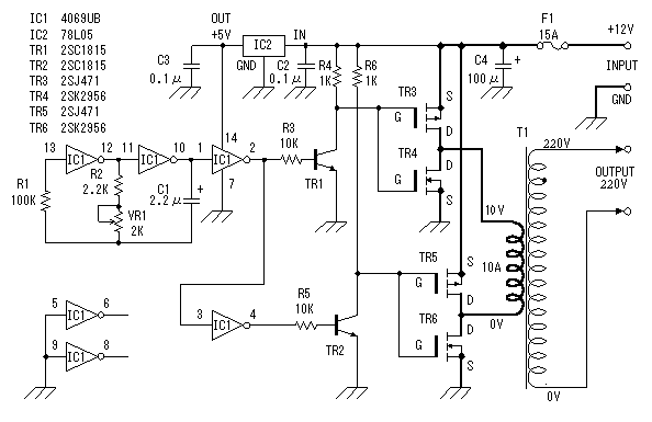
Take a look at the attached circuit ..
You can modify it to suit your needs, but the idea is there ..

Regards,
IanP

please can you help me wth the pin out of that IC1 and IC2? i'm also interested in building one for my use. thanks
 

skema rangkaian inverter 12v to 220v by atlantis

I found a very good 500W mosfet based Inverter

which is simple & relibel


**broken link removed**
 

12dc to 220ac inverter

ummm, what power (Watts) is your load?? is very important this parameter.
 
  • Like
Reactions: rajjut

    rajjut

    Points: 2
    Helpful Answer Positive Rating
12v dc to 220v ac converter circuit

Hi, please i need it also
 

12V DC to 220V AC inverter circuit but 3 phase

How would one go about this problem. Producing a three phase circuit that runs on a 12v battery and could power a 1kw three phase 220 electric motor.

It's seems like quite a challenge. Single phase doesn't prove too much of a problem but three phase seems a real headache.

Any ideas or should i change subjects and just study c++ or something like that.

Thanks
 

Re: inverter schematic watts

How can I make its output 220 VAC 60hz, Sinwave at 8000 watts?

Best Wishes
Tim
 

hi am wondering if anyone can help me.

Am building an high frequency switching inverter using the tl494,and using a H bridge,

can anyone assist me on how the H bridge converts dc back into ac, i mean how do i do this, and how do i get 50hz from this, many thanks

12vdc.....tl494...push-pull mosfets....transformer...bridge rectifier...h bridge...lc filter..

what i need to know is how to switch 2 on and 2 off at same time resulting in ac 220v 50hz, if u know
what i mean

this is a mod-sine wave btw

many thanks
 

Re: Converter 12v dc / 220v AC schematic.

Hi,
Using power transistors will cause plenty of heat. It's better that MOSFETs are used.
Take a look at this:
47_1263278036.gif


Added after 38 seconds:

But, if you're looking for something high performance, you should be using a PWM chip like SG3525/SG3526.

Added after 20 minutes:

Using four MOSFETs helps to use a lower cost transformer. If you use two MOSFETs, you'll need a transformer with centre-tapped 10v.

Added after 14 minutes:

KRYCHEK said:
hi am wondering if anyone can help me.

Am building an high frequency switching inverter using the tl494,and using a H bridge,

can anyone assist me on how the H bridge converts dc back into ac, i mean how do i do this, and how do i get 50hz from this, many thanks

12vdc.....tl494...push-pull mosfets....transformer...bridge rectifier...h bridge...lc filter..

what i need to know is how to switch 2 on and 2 off at same time resulting in ac 220v 50hz, if u know
what i mean

this is a mod-sine wave btw

many thanks
Hi,
The setup will be:
12VDC > Inductor > Capacitor Bank > 12V DC Power
12V DC Power > TL494 > Push-Pull MOSFETs > Ferrite Transformer > Bridge Rectifier > Inductor > High Voltage DC Bus Output of around 300v for 220vac required output.
12V DC Power > 50Hz Oscillator > MOSFET Hi-side, Lo-side Driver > H-bridge > Inductor-Capacitor Filter > Required output voltage.
Hope that's cleared.
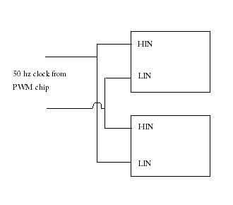
For 50Hz oscillator, I don't think you should use TL494 as it would be outside the specified frequency range in the datasheet. Instead use KA3525(!not SG3525) or SG3526. It has two outputs. Connect these to two hi,lo side MOSFET drivers(IR2110/IR2113/L6384/L6385/L6387).
Take a look at the circuit and carefully go through the datasheet of the hi/lo drivers.
52_1263280112.jpg

I've done plenty of switching inverters like this. If you have any questions/queries, you can ask over here.
Hope this helps.
Tahmid.
 
Thanks for ur answer tahmid, but i still dont understand y i cant used tl494 for this application, i have reverse engineered an inverter, and the h bridge i dont understand
 

If u could please do a description

how does the high frequency get converted into 50hz msw

why are h bridge used

and how to connect the h bridge to get ac


thank u very very much, once cracked i will post the reverse engineered inverter on here
 

Ok,
You're using SMPS, and here you're using a ferrite transformer instead of the bulky iron core ones.
Ferrite transformers only work in high-frequency, not low-frequency.
So, usually around 30 to 50kHz frequency is used to step up the battery voltage from 12v to 300v by using TL494 or any PWM IC and MOSFETs in push-pull or h-bridge configuration. This 300v is high frequency alternating current (AC), usually 30 to 50kHz. So, you can't use this to power your devices.
So, this high frequency AC is converted to DC using ultra-fast recovery diodes and capacitors and inductors for filtering.
The DC needs to be converted to 50Hz AC so that you can use this for your appliances.
To convert this DC to AC, the H-bridge is used.
The H-bridge is driven by the 50Hz clock. I said not to use TL494 here as the datasheet states minimum safe operating frequency of TL494 is 1kHz. You can use KA3525, it's quite similar.

Added after 1 minutes:

Hope you understood.
 

Right wait... so u mean i can still use the tl494 in the circuit BUT, to use the ka3525 to drive the gates on the H-bridge (min 60hz) on the datasheet, is this correct ?
 

A step-down transformer works as a step-up transformer by swapping the primary and secondary windings. The ratio stays the same of course because that is determined by the number of turns on each winding. You may not get exactly the voltage you expect though for these reasons:

1. There are losses in the power transfer of the transformer so you may have to feed more current into the low voltage side than you think. Bear in mind that the extra current will cause more loss through the wire resistance.

2. Step down transformer output voltage is specified under load, it will typically be 5% to 10% above the rated voltage if not loaded. This will influence the voltage you get out when running it in step-up mode.

Also consider that in normal use, power transformers are fed with fairly clean sine waves but all the inverters mentioned so far use square wave switching. This will result in higher loses in the transformer core and hence more power will have to be fed in to overcome it.

If I was designing a square wave inverter like the one using the crystal oscillator mentioned earlier, I would remove all the 50Hz generating circuit and replace it with a PIC10F202. It has a built in oscillator which is quite accurate and stable and a very simple program can generate the bi-phase 50Hz signals. It would even be simple to introduce a dead period between cycles which might improve efficiency.

Brian.
 
Hi KRYCHEK,
You can use the TL494, and I've seen it being used, but it's better not to.
KA3525 better.
I use a small microcontroller here.
You can also use a 4047.
But for 30kHz to 50kHz, you need to use either TL494 or KA3525 or any PWM IC.
 

TAHMID please understand where i need issues been solved

i know the tl494 is running at very high frequencies,

can i use ka3525 ONLY TO SWITCH THE H-BRIDGE MOSFETS @60HZ IN Order to gain this frequency.

so to refresh i am using both ics TL494 AS THE MAIN IC TO GENERATE PWM

AND KA3525 JUST TO DRIVE THE H-BRIDGE

PLEASE TELL ME IF THIS IS POSSIBLE

THANKS TAHMID

Added after 26 minutes:

Another way to look at it is,

THE CIRCUIT IS RUNNING AT HIGH FREQUENCIES..... USING TL494

HOW DO I GET 50HZ,

hope u undertand where i am going wrong
 

Status
Not open for further replies.

Part and Inventory Search

Welcome to EDABoard.com

Sponsor

Back
Top