Continue to Site

Welcome to EDAboard.com

Welcome to our site! EDAboard.com is an international Electronics Discussion Forum focused on EDA software, circuits, schematics, books, theory, papers, asic, pld, 8051, DSP, Network, RF, Analog Design, PCB, Service Manuals... and a whole lot more! To participate you need to register. Registration is free. Click here to register now.

[SOLVED] How to reduce noise from the amplifier(s)?

Status
Not open for further replies.
Hi,

Can you give me some specific recommendations regarding the audio type electrolytic capacitors and for the non polarized aswell?
--> look at your distributor. Simply search for "electrolytic audio capacitor".

Again, can you recommend some specific HF RC Filters? (A brand or something). Thanks a lot for your help :)
R = Resistor, C = capacitor, HF = high frequency. --> No special brand. Try to use what you have by hand.

Klaus
 

I've listened to your recording. There is very little noise without inputs connected, this means that the noise comes from the wiring to the mic and not from the amplifier. If you change things in the amplifier you will see no improvements. You have to improve the wiring to the mic's.
 

I've listened to your recording. There is very little noise without inputs connected, this means that the noise comes from the wiring to the mic and not from the amplifier. If you change things in the amplifier you will see no improvements. You have to improve the wiring to the mic's.

The mic is just attached the circuit with the pre-attached wires on the mic. Maybe I should just change to a better mic, but can you recommend a good mic? :)

Well, I believe that noise is very loud, even thought the mic is not attached. When I attach the mic the noises do not get louder, they are still the same, but they "interrupt" the sounds that the mic is catching/sending.

It is quite simple; if the noise is there when the amp have no wires or inputs then the noise is from the amp. If the noise is there only when you connect the wire or the mics then the noise is from the mics. Of course it can be that both the mics and the amp cause the noise.
Electret mic are quite good for sound quality. If you mount them more than a few centimeters away from the amp you have to have a pre-amp near the mic with output signal not less than 10mV. Now you can hear radio because the input to the amp is too sensitive, only a few mV.
The buzzing noise could be from the power supply. If you use switch mode PS then you have to have good filtering including common mode coils. If you don't need high power speaker then 50Hz power supply is OK.

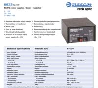
The powersupply is a switch mode (see attached image). I have experienced before that other power supplies made some noise and the I choose this one, cause it seemed like it didn't cause such noise problems.

The speaker unit it self is a small 2.5w.

I got no idea how all that filtering is working. I guess I need some professional help - can anyone recommend a person or a company for that?
 

Hi,

If you have a 50 Hz non switch mod by hand, then please test it.

Klaus
 

The noise is a buzz (something like a trianglewave) at the electrical frequency of 50Hz or 100Hz. It is not smooth hum (sinewave) picked up by unshielded wiring, instead it is probably caused by the power supply not having enough capacitance at the output of the rectifiers or the input voltage to the voltage regulator is too low for it.

The volume control and RC filter parts do not have names like VR1, R23 and C12 so I cannot say anything about them.
It is impossible to follow your pcb design without seeing your schematic, please post it with all the details like the power transformer output voltage and voltage regulator part numbers.
What is the amplifier supposed to amplify? Voices?

- - - Updated - - -

Your first pcb has IC1 what looks like a linear voltage regulator IC. Its input is fed from 3 rectifier diodes and has a small 480uF electrolytic capacitor and a 100nF capacitor. What is its part number and what AC voltage feeds the rectifiers? It is supposed to filter out any AC from the recifiers if its input DC voltage is high enough for it.

The second pcb also has another IC1 what looks like a linear voltage regulator IC. Its input has a tiny 220uF capacitor that is probably much too small and produces the buzzing noise.

I do not see a SMPS and do not know why you have it since the linear voltage regulator is there.
 

The noise is a buzz (something like a trianglewave) at the electrical frequency of 50Hz or 100Hz. It is not smooth hum (sinewave) picked up by unshielded wiring, instead it is probably caused by the power supply not having enough capacitance at the output of the rectifiers or the input voltage to the voltage regulator is too low for it.

The volume control and RC filter parts do not have names like VR1, R23 and C12 so I cannot say anything about them.
It is impossible to follow your pcb design without seeing your schematic, please post it with all the details like the power transformer output voltage and voltage regulator part numbers.
What is the amplifier supposed to amplify? Voices?

Thanks. The power supply is this one(see attached image). It should be able to deliver more than enough power? The volt i currently set to 16 volt.

The voltage regulator is this one: UA7812CKCS (Texas Instruments)

It is supposed to amplify "crying babies / baby noises" and to be totally silent, when they do not cry :D


-Updated.

The IC1 is an amplifier? (LM741) On both circuit boards.
 

Your power supply should be good enough if it is working properly.
I am waiting to see your detailed schematic.

That's almost impossible for me to get, cause it's different material on the internet, that has been put together :/

I am just not satisfied with how the sound is anymore. I want it to be crystal clear(almost at least). I want a system like now; a microphone on which you can specify what channel it is sending to(1-3) and a speaker unit on which you can choose between the 3 channels. You need to be able to connect up to 6 microphone together(2 mics on channel 1, 2 mics on channel 2 and 2 mics on channel 3) and you need to be able to connect like 1-8 speaker units to that system aswell.

As a bonus I would like a LED to light up for 10 seconds on the speaker unit, when the mic register a high tone(a baby crying). Then you know if the sound came from channel 1, 2 or 3 and you know where the crying baby is located.

Would also be perfect if the microphone turn on/start recording, when the sound is high enough. That level should be adjustable.

How much will it approximately cost to design such a system from scratch?
 

It sounds like you want somebody to design a "Nurse-call Audio System" for you instead of you buying one that is already designed and built.
Now I think you have long unshielded wires to many microphones and the electricity hum picked up by the wires is overloading the opamps causing the hum to be a buzz. If you use shielded audio cable instead of ordinary wires to the microphones then there will not be any buzzing noises and "radio" pickup will also be gone.

Maybe the microphones do already have shielded audio cables but you are connecting them backwards so that the shield is picking up the buzzing and interference. The shields are supposed to connect to the circuit 0V, ground.

If you get the audio working properly then comparators and timers can be added later for LEDs to light when there is sound.

Well the sound is good now - not sure where the mistake was made, maybe just because I didn't connect a mic and turned up the volume and activated all 3 channels.

Well now I have tested the TL071 and the NE5534, and it do change the sound quality a bit, since I can hear it with my own ears. It gets clearer for sure.

What I need now is to be able to lower the rate at which the microphone catch/record the sound. How can I adjust the level on the microphone? Cause it's like it can hear what's happening kilometers from where it is located. It can hear sounds that the normal ear cannot hear.

Should I change the 2,5k Trimmer on the mic circuit? When I turn the speaker-unit to max it starts scratching, so I lowered the 42k to 22k. But is there another way to fix that problem?
 
Last edited:

What I need now is to be able to lower the rate at which the microphone catch/record the sound. How can I adjust the level on the microphone? Cause it's like it can hear what's happening kilometers from where it is located. It can hear sounds that the normal ear cannot hear.

That's the property of an electret microphone. It is very sensitive. If you want to pass only speech through the amplifier, you can design a LPF at the input of the amplifier who's cutoff frequency lies between 2.5 - 3 kHz.
 

That's the property of an electret microphone. It is very sensitive. If you want to pass only speech through the amplifier, you can design a LPF at the input of the amplifier who's cutoff frequency lies between 2.5 - 3 kHz.

Nice, gonna look into that - is it complicated? :D

Thanks a lot for the reply :)
 

LPF is a Low Pass Filter.
Formulae:

fc = 1 / (2*pi*R*C)
fc = 3000 Hz (Cutoff Frequency of the LPF)

Consider a value for C, to get the value of R.
If C = 10nF, R ~ 5300 Ohms. (Consider 5.6 kOhm)
So with these standard components, your cutoff frequency becomes ~2.8 kHz.

Making this modification will make the sound a bit muddy, since the high frequency components in the signal are rejected by the LPF.
 

Should I change the 2,5k Trimmer on the mic circuit? When I turn the speaker-unit to max it starts scratching, so I lowered the 42k to 22k. But is there another way to fix that problem?
The first circuit board you posted has an LM380 power amplifier fed from Pot M-10k which is its volume control. Simply turn down the volume control to reduce the sensitivity of the microphones.
When the value of the 42k resistor is reduced then the gain of its opamp is reduced that also reduces the sensitivity of the microphones.
It is the electronic circuit that is very sensitive, not the electret microphones.

On the second circuit board you posted there is a box labelled P1 that is a gain control for its opamp (maybe it is the 2.5k trimmer you talked about?) that also reduces the sensitivity of its microphone.

Babies cry at 1kHz to 3kHz audio frequencies so you do not want a lowpass filter to reduce it. You might want a 10kHz lowpass filter to reduce hiss and a 200Hz highpass filter to reduce hum and rumble.


What you just said there made a lot of sense - even thought I am half retarded to this stuff it made sense.

I have figured out that it might be a too big project for me to learn - so I will find a company that can make a solution :) Thanks a lot everyone for the help so far :)

Have a great new year :)
 

Status
Not open for further replies.

Part and Inventory Search

Welcome to EDABoard.com

Sponsor

Back
Top