Continue to Site

Welcome to EDAboard.com

Welcome to our site! EDAboard.com is an international Electronics Discussion Forum focused on EDA software, circuits, schematics, books, theory, papers, asic, pld, 8051, DSP, Network, RF, Analog Design, PCB, Service Manuals... and a whole lot more! To participate you need to register. Registration is free. Click here to register now.

How to make (build) ATS (Automatic Transfer Switch) ?

Status
Not open for further replies.

phatcreators

Full Member level 5
Full Member level 5
Joined
Sep 2, 2011
Messages
315
Helped
24
Reputation
48
Reaction score
24
Trophy points
1,298
Activity points
3,458
How to make (build) ATS (Automatic Transfer Switch) ?

I want to switch off my generator's output power & switch on the electricity (provided by the Govt) when the electricity shortage (outage) is over . Can i make that circuit ?

Also, if i want to completely shut off the generator then can it be done too ?
 

Automatic transfer switch - these are used on professional applications. The circuit is at its simplest is a change over relay with its coil wired to the mains. When there is mains incoming the relay is energised and its contacts select the incoming mains. when there is no mains, the relay is de-enegised and the generator output is selected.
When a diesel generator goes off load (mains returns), a timer runs for 10 Minutes, allowing the generator to cool down, then the fuel relay is de-enegised so starving the engine of fuel so it stops. With petrol engines just break the ignition circuit with a relay.
Frank
 
would you provide me the schematics of ATS for a petrol & for a Natural gas generator ?

What safeties must be take into action while designing & connecting ATS with generators ?
 

answer at the earliest of the questions that are asked in post no.3 please, if any ?
 

The safety precautions are that you must make sure that there is no possibility of the generator or the mains being connected together. For high current cicuits when a single changeover relay cannot be used, say over 30A. Then a pair of contactors have to be used, only one at a time being selected. To overcome the unlikely problem of one of the contactors having its contacts welded together, i.e. when the other contactor is energised, the first one is still jammed in, the contactors are supplied as a mechanically interlocked pair, so it is physically impossible to have both selected at once. Also if the mains are being worked on so you are running on the generator you don't want to be feeding mains "backwards" down the mains wire to electrocute any of the workers. With automatic running you must have some sort of indication/alarms so the state of the oil, fuel, engine temperature... can be seen because you might be running on the generator so you check these out without breaking your supply (cos' the mains is off!!)
Frank
 
  • Like
Reactions: valuty

    valuty

    Points: 2
    Helpful Answer Positive Rating
what about the schematic or any related circuitry with the ATS ? Also about the connections or the circuitries of the safeties which are to be used ?

thanks though a lot
 

kindly do provide me the required circuit so that i could be able to make an ATS for my portable generator ?
 

In order to start designing such circuit you need to provide more details.
First what’s the maximum power load? How much power can the Generator supply?
Secondly, how do you expect to control the power generator? Can you provide a wiring diagram for this unit?
 

max. power load is 7.5 Amps at 230 Vac ....... power the generator can supply is almost 10 Amps at 230 Vac

i can't provide the wiring diagram but i do explain it

i want to start my generator automatically when there is power shortage or failure and want to shut it off when the power is alive or come for my house ..... its a portable home generator .....
 

Missing one important detail, that’s a pull start generator or the generator include some electric starter? :)
 

it has both the recoil (rope) manually & electric starter with the help of key (ignition)
 

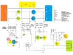
Here you find attached a diagram using 12V relays and step-down transformers. In practice there are many important details/timings related to the generator start / stop particular procedures to fix in order to get a fully functional circuit. ;-)
 

Attachments

  • ATS_v3.png
    ATS_v3.png
    170.3 KB · Views: 380
thanks a lot buddy , wouldn't it be enough (the circuit that you provided me in the last post) as i told all the related info ?

What other related details you're referring at ? Related to my case (home portable generator)
 

what would be the building cost of this above provided schematic & the circuit ?
 

You need to consider that’s not a final product, that’s more a proof of concept necessary to gives us an idea of what the final system looks like. :grin:
Also need to consider such a device must be modified to suit specific generator START /STOP operations, this means you need to have access to all the generator technical documentation. For example in this diagram still is missing a temporized relay to stop the generator after a delay of several minutes in order to allow cooling for. All the tests and necessary adjustments are time consuming, and must be carried on the field. As usual can be expected that individual prototype costs will be substantially greater than the final production costs due to inefficiencies in materials and processes.
 

building cost of it would be ?
 

Frankly, I don’t know. :-D
There are many possibilities to build such a project, you can use the high quality components on the market (!!) and the price will go high, or just using some second hand parts and obtaining a lower costs.
Just in case we may start preparing a shopping list:
2 24V/16A-25A Main contactors
3 230Vac/24Vac transformers
4 1 amp rectifier bridge
1 24V relay
1 temp relay
1 DPDT switch
12 terminals block
1 box
Some capacitors/resistors/fuses (fuses= very important details missing on the above diagram :roll: )

Labor work is also very difficult to estimate, usually such a DIY project will be for free (if you have enough time to spend for), or you may end up paying someone for a full day of work.
 

so , what about the fuses ? As they're missing in the above provided diagram ..... so where to put them & of what capacity ?
 

Status
Not open for further replies.

Similar threads

Part and Inventory Search

Welcome to EDABoard.com

Sponsor

Back
Top