Continue to Site

Welcome to EDAboard.com

Welcome to our site! EDAboard.com is an international Electronics Discussion Forum focused on EDA software, circuits, schematics, books, theory, papers, asic, pld, 8051, DSP, Network, RF, Analog Design, PCB, Service Manuals... and a whole lot more! To participate you need to register. Registration is free. Click here to register now.

[SOLVED] How to import s2p file into NPORT element of Cadence Spectre and achieve correct simulation result?

Status
Not open for further replies.

aminaminy

Newbie
Joined
Apr 26, 2024
Messages
5
Helped
0
Reputation
0
Reaction score
0
Trophy points
1
Activity points
38
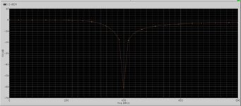
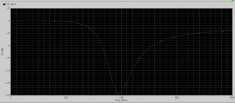
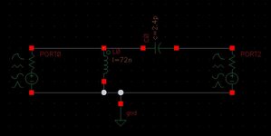
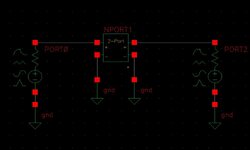
In the schematic environment of Cadence Spectre software, I simulate a simple impedance matching circuit that matches a 50 Ω load to 600 Ω. (Schematic1.jpg). The S-parameter simulation(S11) result is shown on result1.jpg. It is clear that the impedance matching is well done at 400 MHz. I save the output results in touchstone format(db/phase) and in the s2p file. In the new cell view(Schematic2.jpg), I perform the same analysis using the n2port element and importing the previously obtained results file. However, this time the S11 output is not at all the same as the previous simulation. I don't know what's wrong. Please correct me if I import the file wrongly or any mistakes are present on set up.
 

Attachments

  • Result1.JPG
    Result1.JPG
    179.8 KB · Views: 37
  • Result2.JPG
    Result2.JPG
    164.5 KB · Views: 36
  • Schematic1.JPG
    Schematic1.JPG
    39.6 KB · Views: 36
  • Schematic2.JPG
    Schematic2.JPG
    42.8 KB · Views: 40

It's an interpolation problem. You have to simulate your RLC circuit with smaller frequency steps.
Because Spectre interpolates s-parameters during frequency band and this error occurs in second simulation testbench.
Don't be afraid, use much smaller frequency steps to get much healthy results.
 

It's an interpolation problem. You have to simulate your RLC circuit with smaller frequency steps.
Because Spectre interpolates s-parameters during frequency band and this error occurs in second simulation testbench.
Don't be afraid, use much smaller frequency steps to get much healthy results.
Thanks for your suggestion. This time I used 10000 steps to make sure everything is fine, But had no luck to see the correct result, and unfortunately the second chart still shows wrong data.
 

simple impedance matching circuit that matches a 50 Ω load to 600 Ω.
Make sure that you set both ports to 50 Ohm (!) when creating the S2P data.
Mixed port impedance for S2P is not supported by many tools.

Of course, in your testbench where you use the S2P elements you can use mixed port impedance, but not when creating the file itself.
 
Thanks. it was exactly the reason why data shown was not correct. In this example when I set both port impedances to 600 ohms, It plots correctly.
But how should one possibly use the model for mixed port impedances?
In this simple example, in order to match 50 ohms load to the 600 ohms source impedance, My goal is to replace the RLC matching network with the obtained S11 results imported into the n2port element.
 

But how should one possibly use the model for mixed port impedances?
Just use the data and don't worry. The S2P data block performs correctly under all possible source and load impedances, even mixed impedance. The testbench source and load impedance can be very different from the impedance used to create the S2P block, that is perfectly valid.

The issue is that you used mixed impedances to create the S2P data, but the definition of the S2P file format doesn't support that.
 
Last edited:
Thanks. it was exactly the reason why data shown was not correct. In this example when I set both port impedances to 600 ohms, It plots correctly.
But how should one possibly use the model for mixed port impedances?
In this simple example, in order to match 50 ohms load to the 600 ohms source impedance, My goal is to replace the RLC matching network with the obtained S11 results imported into the n2port element.
OK, I missed the port impedances. You set Port1 to 600 Ohm, Port2 to 50 Ohm.
You cannot do that. Spectre n-port device accepts-IMHO- Touchstone or similar s-parameters definition format and there is only ONE Port Impedance in it.
So you should enter either 50 Ohm OR 600 Ohm but not both. If you check Touchstone file by notepad, you will see that the Common Port impedance.
ADS creates mixed mode touchstone file.
1714263336340.png

You have to search maybe a different format than Touchstone 1.0. There might be some options to convert this onto 2.0
 
Last edited:
Just use the data and don't worry. The S2P data block performs correctly under all possible source and load impedances, even mixed impedance. The testbench source and load impedance can be very different from the impedance used to create the S2P block, that is perfectly valid.

The issue is that you used mixed impedances to create the S2P data, but the definition of the S2P file format doesn't support that.
Thank you very much for your help. Yes I set both ports impedance to 50 ohms for simulation and imported the created s2p file again and this time it gave the correct result for 50 to 600 match.
 

OK, I missed the port impedances. You set Port1 to 600 Ohm, Port2 to 50 Ohm.
You cannot do that. Spectre n-port device accepts-IMHO- Touchstone or similar s-parameters definition format and there is only ONE Port Impedance in it.
So you should enter either 50 Ohm OR 600 Ohm but not both. If you check Touchstone file by notepad, you will see that the Common Port impedance.
ADS creates mixed mode touchstone file.
View attachment 190427
You have to search maybe a different format than Touchstone 1.0. There might be some options to convert this onto 2.0
Yes I figured out that was the reason. ADS supports mixed port but Spectre does not. But that's not problem. Solution is straight forward.:
Just design the circuit for desired spec,
replace port impedances to 50,
Simulate and create the S2p file.
Import the output file into the nport element inside new cell view.
Now set the desired ports impedance to the initial original values and everything works fine.
 

Status
Not open for further replies.

Part and Inventory Search

Welcome to EDABoard.com

Sponsor

Back
Top