Continue to Site

Welcome to EDAboard.com

Welcome to our site! EDAboard.com is an international Electronics Discussion Forum focused on EDA software, circuits, schematics, books, theory, papers, asic, pld, 8051, DSP, Network, RF, Analog Design, PCB, Service Manuals... and a whole lot more! To participate you need to register. Registration is free. Click here to register now.

How to implement a transfer function with discrete components

Status
Not open for further replies.
OK thanks. Just for information, how is a LHPZ + single pole combo of unequal pole/zero frequency realized pls?

See comparison of standard all-pass and unequal (lhp)pole/zero circuits
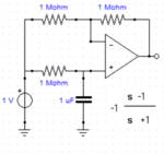
pz1.PNG pz2.PNG

And just in case I needed to implement the TF in 'z' domain, how could I do so?
Not possible with simple discrete circuit. Applies either to digital signal processing or switched capacitor circuit.

Which discrete op amp IC would you suggest for physical realization of the TF? Though there are many op amps available, which one would be adept in the job?
Any general purpose OP.

Finally during testing, what characteristics does one need to check for a filter? I know mainly about 3 dB frequency and that the roll down/up rate to be 20dB
Still not sure what's your application for the transfer function, what are the involved signals and respectively what kind of test is useful.
 

See comparison of standard all-pass and unequal (lhp)pole/zero circuits
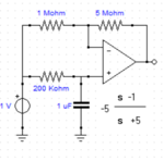
View attachment 151196 View attachment 151197

OK. Thanks for the clarifications. I could calculate the values of DC gain and pole here (inverting gain of the amplifier and -1/RC). How to calculate (or basically select components) for the value of zero (zero at 1).

Also to implement a pole, one could use either a first order low pass or integrator ckt. Which one to prefer when? Similarly for implementing a zero, one could use a first order high pass or differentiator ckt. Which one to use when?

I myself don't know the use of the TF. I was just given to just implement it on the bred board and see if it can be realized.

Regards,

Arvind Gupta
 

I myself don't know the use of the TF. I was just given to just implement it on the bred board and see if it can be realized.
O.K., just an exercise. As you see, it can be implemented.

There are however additional problems related to input signal level and OP voltage swing. The given circuit has some gain of 5 the first stage and gain < 1 in the second stage, thus there's a chance to get signal clipping in the first stage output. One possible solution is to flip first and second stage, or implement the transfer function in a different way, depending on the actual requirements.
 

OK. But the basic question remains. How to select circuit values for fixing the zero at s=1 in your last two ckt diagrams (and in my TF)?

Regards,
Arvind Gupta
 

As long you are doing an exercise without actual requirements, absolute component values don't really matter. I started with feasible capacitor values in my example.

As for relative component values (resistor ratios, RC time constants), I sketched my method in post #19:
- have a principle circuit topology and it's general transfer function
- apply comparison of coefficients
 

Status
Not open for further replies.

Similar threads

Part and Inventory Search

Welcome to EDABoard.com

Sponsor

Back
Top