Continue to Site

Welcome to EDAboard.com

Welcome to our site! EDAboard.com is an international Electronics Discussion Forum focused on EDA software, circuits, schematics, books, theory, papers, asic, pld, 8051, DSP, Network, RF, Analog Design, PCB, Service Manuals... and a whole lot more! To participate you need to register. Registration is free. Click here to register now.

How to identify a broken zener diode?

Status
Not open for further replies.
From the number of unknowns transistor part number and no schematic, you need more experience to debug this.

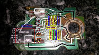
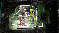
I started a rough schematic using PSP7 (paint shop pro7) line up your pictures to flip the bottom and make the top partially transparent. then crudely trace the lines ( 15 min)

If you want to learn how to debug, get the transistor part numbers, maybe cap values then it might be possible to make a more readable schematic.
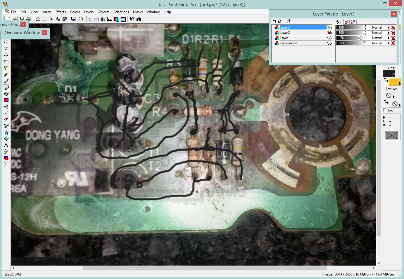
8919004100_1442757578.jpg
 
  • Like
Reactions: Choose

    Choose

    Points: 2
    Helpful Answer Positive Rating
Thank you very much SunnySkyguy. Your involvement has motivated me. :thumbsup:

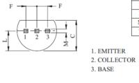
I was finally able to read the ID of the second transistor (A1266) but now I am even more puzzled. The leads work contrary as they should according to the datasheet, and the middle one gives no reading. That means two things: that I should perhaps look for a replacement, and that I might have placed the BC338 the wrong way...

I need to look for the old C3202 and see if it gives me a valid reading to know which lead is the base... It is crazy not to be able to be sure of any polarity...

This is my first attempt to draw a diagram. The switch action is not displayed... yet. :oops: I hope it is useful. The back side is flipped in order to fit the diagram. The white path is for the back side, and the black path is for the front side (I got lost when I reach the relay).


As an update, I believe that the BC338 is correctly placed. On the other hand, the A1266 does not seem to work as the datasheet states.


My test gives as result an EBC setup. I think I am not wrong about the base because tracks that end at base legs of both transistors are especially damaged.

So now, datasheets are not a trustworthy source... Great.
 

The Korean datasheet you posted did not say what I found on another datasheet:
 

Attachments

  • 2SA1266 transistor pins.png
    2SA1266 transistor pins.png
    18.3 KB · Views: 90
  • Like
Reactions: Choose

    Choose

    Points: 2
    Helpful Answer Positive Rating
Status
Not open for further replies.

Part and Inventory Search

Welcome to EDABoard.com

Sponsor

Back
Top