Continue to Site

[SOLVED] How to design variable resistors R0 to represent the frequency-dependent loss in ADS

Status
Not open for further replies.

thundrous

Junior Member level 3
Joined
Oct 16, 2022
Messages
25
Helped
0
Reputation
0
Reaction score
0
Trophy points
1
Activity points
227
I am trying to replicate a result of a paper in Advanced Design System software. It is mentioned that the resistance is variable and its equation is 10e-9f (GHz) + 5.
Screenshot 2023-01-24 212907.png

When I drew the resistance in the software and wrote the formula, a syntax error showed up.

Would you please guide me on how to enter this equation? Is there any specific module I need to enter inside the equation field?

Here is their equivalent circuit:
Screenshot 2023-01-24 214536.png

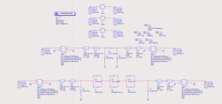
and here is the equivalent circuit that I drew:
Screenshot 2023-01-24 213547.png


I would appreciate it if you please help me.
 

Use equation based s-parameter blocks.
Define first s-parameters matrix of a series resistor then enter these values into equation based blocks with the variable "freq". Otherwise it will not recognize.
 

Use equation based s-parameter blocks.
Define first s-parameters matrix of a series resistor then enter these values into equation based blocks with the variable "freq". Otherwise it will not recognize.
Thank you very much for your response, until now I updated the equivalent circuit as follows, but still I cannot reach the proper data. Do you have any idea where the problem is? Also, i do not know how to introduce the frequency as the variable "freq". I tried to but the software does not accept it.
any suggestion appreciated.

1674695530575.png


1674695587598.png

1674695623962.png
 

S-parameters matrix of a series resistance ;
1674707534288.png

Here Z=R in your case.
Then use equation based s-parameter block like this.
1674708254041.png

then you will see that s-parameters are not constant versus frequency. (If the resistance was constant, s-parameters should have been constant too but they aren't due to frequency dependence of the resistance)
1674708586752.png
 

S-parameters matrix of a series resistance ;
View attachment 180869
Here Z=R in your case.
Then use equation based s-parameter block like this.
View attachment 180870
then you will see that s-parameters are not constant versus frequency. (If the resistance was constant, s-parameters should have been constant too but they aren't due to frequency dependence of the resistance)
View attachment 180872
Thank you very much for your guidance I did what ever you mentioned in the previous comment as follows based on my current device and here is my Equivalent circuit:

1674754915668.png


S21, S11 are my experimental results and S65, S55 are for the simulation

1674754866763.png


I've got a good verification between S21 and S65, However the S55 does not seems good and it starts from -10dB
So based on the article I changed the frequency loss resistance depedance as follows: I eleiminated R=50
1674755289189.png

then the slope of S55 changed but still it starts from -10dB. It seems the variable Rlossy has lots of effect on our measurments and by changing the formula i even needed to change the capacitance C4 for validation between simulation and experiment results.


1674755235088.png


Would you please guide mewhich one is current and where did I made a mistake because S55 should start from zero.
 

Attachments

  • 1674754604649.png
    1674754604649.png
    80.5 KB · Views: 212

It was my own example, not real/your one. You have to define your own formulae by yourself. It might
be anything as you desire. I dont know the process that you've been working on.
 

I would model this as S1P data block, using Z parameters in real/imag format for easy data entry.

# GHz Z RIR 1.0
0.00 5 0
1.00 6 0
2.00 7 0
10.0 15 0

In ADS that S1P block is connected as a series element using both terminals (signal and ground).
 

I do not know, would you please explain more?
If it's a real resistor then it has real inductance and perhaps
modeling it that way gets you where you need to go. The
stated behavior seems consistent with that (though whether
a simple lumped, or more fine grained network suits your goals
I could not say)
 

Status
Not open for further replies.

Part and Inventory Search

Welcome to EDABoard.com

Sponsor

Back
Top