Continue to Site

Welcome to EDAboard.com

Welcome to our site! EDAboard.com is an international Electronics Discussion Forum focused on EDA software, circuits, schematics, books, theory, papers, asic, pld, 8051, DSP, Network, RF, Analog Design, PCB, Service Manuals... and a whole lot more! To participate you need to register. Registration is free. Click here to register now.

[SOLVED] how to convert AC to DC forinput to ADC

Status
Not open for further replies.
I repeat, the only difference between AC and DC is that the AC swings from minus voltage to positive voltage, if you have a sinusoidal of 5v peak to peak then the swing is from -2.5v to +2.5v, if you add a DC offset of 2.5v then the swing becomes -2.5v+2.5v to +2.5v+2.5v where +2.5v is the offset.

in the schematic of my previous post feed the AC input to V2, V1 to GND and Vr to +2.5v.
If you don't want gain then set all resistors to 1K

A typo should be written as, if you add a DC offset of 2.5v then the swing becomes from 0 to +5v.
 

What do you mean?

I wrote to him in post #2
You have to attenuate the voltage to about 5v peak to peak and then add an offset of 2.5v so that it becomes 0 to 5 instead of +-2.5

and then I have explained this further in post #4
if you have a sinusoidal of 5v peak to peak then the swing is from -2.5v to +2.5v, if you add a DC offset of 2.5v then the swing becomes -2.5v+2.5v to +2.5v+2.5v where +2.5v is the offset.

I was just trying to explain how the offset adds with the input voltage

Alex
 

As you wrote invpost 2 is ok.
add an offset of 2.5v so that it becomes 0 to 5 instead of +-2.5
In post# 4, isnt it a typing mistake.
if you add a DC offset of 2.5v then the swing becomes -2.5v+2.5v to +2.5v+2.5v

I am just trying to explain if somebody got confused.
Is '+2.5v+2.5v ' not to be '0v+5v'
 
Last edited:

No, what I describe by -2.5v+2.5v to +2.5v+2.5v where +2.5v is the offset.

is negative Vpeak+Voffset which is -2.5v +2.5v =0v

and positive Vpeak+Voffset which is +2.5v +2.5v = 5v

Alex

Added: Both parts describe the resulting swing not the before and after swing but I can understand what you say although I did define that the blue number was the offset
 
Last edited:

I made the circuit but it did not work
the design file is attached,
kindly comment


Thanks a lot for helping me out
 

Attachments

  • H circuit.zip
    11.1 KB · Views: 110

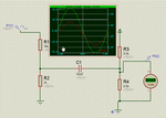
you forgot to connect the Vcc to the upper resistor of the right side divider so there is no offset applied

Alex
 

it is still not working, can u send me file after putting Vcc
thanks
 

You only need to add a Vcc and it works fine

H_divider.gif

Alex
 

In my view an ADC requires an analog signal which is AC but a micro controller requires a DC , if u want both AC and DC first just use a step down transformer of your requirement.Then use a rectifier circuit so that it converts it into DC ,Now before giving to the rectifier just take same voltage given to the rectifier now you have two voltages one AC and other is DC.If the requirement of your AC voltage is higher just use an amplifier with some extended gain.
 

You only need to add a Vcc and it works fine

View attachment 61505

Alex

Thanks a lot Alexen as u helped me all the way to make me understand and spent ur precious time. I just want to close this thread with one last question that i am getting exactly 0 to 5 Volts with this H- Circuit. The R3 and R4 are set to 3.9 K, Why they have been adjusted to this specific value
any calculation for that or any value can work here
i tried 10 K at R3 and R4 and they also worked.
why that person specifically said 3.9 K?
 

The second divider loads the first divider so you will see that the division ratio of the first divider change depending on the values of the second one.
In this case the two 3k9 resistors are seen as a (almost) 2k in parallel with R2 so the first divider becomes 18k/1k

Alex
 

The second divider loads the first divider so you will see that the division ratio of the first divider change depending on the values of the second one.
In this case the two 3k9 resistors are seen as a (almost) 2k in parallel with R2 so the first divider becomes 18k/1k

Alex

It is not clear, plz explain again in other way
thanks
 

well, if you want to get a DC Output from ac. you have to use the full-wave rectifier followed by the filter circuit. the rectifier will convert the bidirectional ac to unidirectional ac, the filter circuit will, then convert this unidirectional ac to dc. then fed this value to your adc.

Note: if you want to give a constant dc supply, use a voltage regulator like 5.1v zener diode or 7805 ic etc after the filter.. Note for 7805, if you fed arround 7v input to its ic only you will get 5v output. It is also advisible to use some filter capacitors in the output of 7805 to filter out the low frequencies and obtain an almost perfect dc.

hope this is helpful
 

well, if you want to get a DC Output from ac. you have to use the full-wave rectifier followed by the filter circuit. the rectifier will convert the bidirectional ac to unidirectional ac, the filter circuit will, then convert this unidirectional ac to dc. then fed this value to your adc.

Note: if you want to give a constant dc supply, use a voltage regulator like 5.1v zener diode or 7805 ic etc after the filter.. Note for 7805, if you fed arround 7v input to its ic only you will get 5v output. It is also advisible to use some filter capacitors in the output of 7805 to filter out the low frequencies and obtain an almost perfect dc.


hope this is helpful

So what abt the technique of H- circuit.
Can i give its output to ADC. Am i going in right direction
Someone said that with offset, the AC becomes DC
 

It is not clear, plz explain again in other way

the second divider works like a load connected to the first divider, with the two 3k9 resistors the resistance load seen by the first divider is 3K9 /2 which is almost 2K, this 2k it connected in parallel to the R2 so you have two 2K resistors in parallel which results in 1K so the actual division factor becomes 18K/1K

Alex

Ok thanks alex it is now clear

and what abt rjkrocks comments

Can i feed H-circuit output to ADC
 

what he describes is a different thing, instead of adding an offset to move the sinusoidal to the positive region (above 0 volts) he says to use a rectifier and rectify the voltage to get a pure DC, a constant peak voltage like when you use a power supply and the AC of the transformer is rectified to a DC

Alex
 

ok that i have understood but i want to ask one thing that if i use rectifier, then ADC of MCU will get constant level which will be wrong technique

I think for ADC, the technique which u told to use Offset is desireable

am i right in saying it
 

These are two different things, if you just want to measure the voltage in the input then there is no point to use the sinusoidal signal, you just need the peak value.
On the other hand if you want to make something like an oscilloscope and show the input to a screen then you have to actually read the complete signal accurately, you may also use this way to measure the frequency of the signal or zero crossing or check symmetry etc.

Alex
 
Please give pictorial representation of the above circuit and send it.i am not able to understand it.

thanks for reply
 

Status
Not open for further replies.

Part and Inventory Search

Welcome to EDABoard.com

Sponsor

Back
Top