Continue to Site

Welcome to EDAboard.com

Welcome to our site! EDAboard.com is an international Electronics Discussion Forum focused on EDA software, circuits, schematics, books, theory, papers, asic, pld, 8051, DSP, Network, RF, Analog Design, PCB, Service Manuals... and a whole lot more! To participate you need to register. Registration is free. Click here to register now.

[SOLVED] How to configure pic 16f72 in micro c compiler

Status
Not open for further replies.
Well, give it a try.
 

Attachments

  • 16F72.zip
    329 bytes · Views: 143
yes sir your hex file is working on my hardware and not give any types of error.
how to solve this problem sir.
i want to know procedure to write .
please help me sir
 
hello sir ,
please tell me how to setting andi want to see your source code .
please help me
 
Hello everyone,
i am new in pic controller programming.
I am doing a project on PIC16f72 and using mikroc pro compiler.
The problem i am facing is, according to datsheet of PIC16f72 the value of config word should be 0x3fb2 in case of external osc(4 Mhz).
i have tried every option of config word setting but still didn't get that value of config word...
It seems me that's why i am even not able to blink a led through micro.
Please help me to overcome from this situation and suggest possible way to sort out it.
 

You will use pickit2 as a programmer.
 

See the attached image. You don't have to worry about unimplemented bits. The Compiler will handle it.
 

Attachments

  • config word.png
    config word.png
    113 KB · Views: 150
not woking itried all thing according datashheet but not get output while i am change pic16f72 insteadof pic16f72 then working but some problem i am facing when i interfaced switch with ic
 

Can't help you without seeing your exact circuit including power supply.
 

Hello,
I can't send complete(due to complexity) circuit but can explaine about it.
One thing,when i choose PIC16f722 in place of PIC16f72 i get same config word 0x3fb2 and get some output using pic16f72 controller.
Now i am able to control four 7 seg and 5 leds.
But now facing another problem.
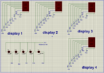
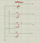
Capture2.PNGCapture1.PNG
Here shown in pics there r 4 7 seg display named displa1,display2 ,display3,display4 and micro pins to whom they connected.
display1 and 2 used for timer purpose(00-99) and 3 and 4 used to show voltage of ADC pic as (0.0 to 5.0)
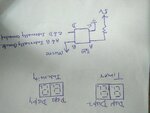
IMG20170107161229.jpg
Iam able to display value(00-99) in timer sec and now trying to increse and decrese it with switch.
But it is not working properly.
here i am posting my code.

PHP:
/************************************* SEGMENT***********************************/
#define pin_a   RB6_bit
#define pin_b   RB7_bit
#define pin_c   RB1_bit
#define pin_d   RB2_bit
#define pin_e   RB3_bit
#define pin_f   RB5_bit
#define pin_g   RB4_bit
#define pin_dp  RB0_bit
 /***********************  LED**********************/
#define led_1   RB4_bit
#define led_2   RB0_bit
#define led_3   RB1_bit
#define led_4   RB2_bit
#define led_5   RB3_bit
/******************** CATHOD *****************/
#define cc_1  RC6_bit
#define cc_2  RC7_bit
#define cc_3  RC3_bit
#define cc_4  RC4_bit
#define led_gnd RC5_bit

/********************  KEY**************************/
#define sw_up  RA4_bit
#define sw_dwn  RA2_bit
#define sw_strt  RA5_bit

#define buzz  RC2_bit
#define relay RA1_bit

unsigned char disp_1[10] = {0xef,0x83,0xdd,0xd7,0xb3,0x77,0x7f,0xc3,0xff,0xf7};
unsigned char disp_2[10] = {0x7f,0x1c,0xbb,0xbe,0xdc,0xee,0xef,0x3c,0xff,0xfe};
unsigned int  ins_unit,ins_dec,dec;
int unit;


void keypad()
{

 if(sw_up == 0)
 {
  if(dec==9 && unit==9);
  else
  {
    unit=unit+1;
    if(unit>9)
    {unit=0;dec=dec+1;}delay_ms(50);
  }
 }
 if(sw_dwn == 0)
 {
  if(dec==0 && unit==0);
  else
  {
    unit=unit-1;
    if(unit<0)
    {unit=9;dec=dec-1;}delay_ms(50);
  }
 }
}

void main()
  {
       int x;
       TRISA = 0b00110101;
       //TRISA = 0xff;
       //TRISA=0b00000000;
       TRISB = 0X00;
       TRISC = 0x00;
       relay=0;// relay 0 to onn and  1 to off
       delay_ms(500) ;
       led_gnd=cc_1=cc_2=cc_3=cc_4=1;
       unit=0,dec=0;ins_unit=0,ins_dec=0;;
       while(1)
       {          
                  for(x=0;x<50;x++)
                  {
                    cc_3=1;cc_2=0;
                    PORTB=disp_2[unit];
                    keypad();delay_ms(5);

                    cc_2=1;cc_1=0;
                    PORTB=disp_1[dec];
                    keypad();delay_ms(5);

                    cc_1=1;cc_4=0;
                    PORTB=disp_2[ins_unit];
                    keypad();delay_ms(5);

                    cc_4=1;cc_3=0;
                    PORTB=disp_1[ins_dec];
                    keypad();delay_ms(5);
                  }

      }
                  

      }

- - - Updated - - -

What problem i am facing is when i put unit =9 ,dec=9....it decreaces automatically from 99 to 00.
 

Hi,

But it is not working properly.
Means what?

Please learn to give exact error descriptions.

Klaus
 

One thing,when i choose PIC16f722 in place of PIC16f72 i get same config word 0x3fb2 and get some output using pic16f72 controller.

For this particular point I have stated earlier that you need not to stick to get configuration word for 16F72 as 0x3FB2. When you compile the code in mikroC with configuration word similar to 0x3FB2, you will get output of 0x12. The compiler ignores the unimplemented bits. However, this will not make any problem in burning the device. skip the verification while burning the device. For this all that you need to do is untick the "Verify After" box of your programmer. See the image. Thus you will be able to burn 16F72 with configuration word of 0x0012 or so.

**broken link removed**

Iam able to display value(00-99) in timer sec and now trying to increse and decrese it with switch.

I am not clear what you are trying to increase or decrease. Give some more detail of your requirement.
 

    V

    Points: 2
    Helpful Answer Positive Rating
Somehow the image was not uploaded properly. It is again uploaded.
 

Have you tried with another pic16f72 microcontroller? just in case if the MCU is damaged.
I am sharing the below configuration settings for PIC16F886 MCU, which you can refer as an example,
Code:
; CONFIG1
; __config 0x20F1
__CONFIG _CONFIG1, _FOSC_HS & _WDTE_OFF & _PWRTE_OFF & _MCLRE_OFF & _CP_OFF & _CPD_OFF & _BOREN_OFF & _IESO_OFF & _FCMEN_OFF & _LVP_OFF
; CONFIG2
; __config 0xFFFF
__CONFIG _CONFIG2, _BOR4V_BOR40V & _WRT_OFF

Ref: **broken link removed**
the example which they have given in the above website, i have tried and it was working.

No, the mcu is not damaged. The configuration word programming fails due to verification mismatch. Just disable the verification step of the programmer and see successful burning. Soon I am uploading the image.
 
  • Like
Reactions: SHADIQUE

    V

    Points: 2
    Helpful Answer Positive Rating

    SHADIQUE

    Points: 2
    Helpful Answer Positive Rating
See the image and act accordingly.
 

Attachments

  • Confg_bit.jpg
    Confg_bit.jpg
    252.4 KB · Views: 121
Yes swapan......it's now flashing the controller and works according to software after untick the varification box.....
Hello klaust...
I have three push buttons in haedware with the help of them i have to increase and decrease the value on timer sections as i shown in picture.
**broken link removed**
I posted my code above....i have many times used same logic with 8051 series controllers and every time i get results.
But here this logic not working for me.....As i mentioned earlier i am not much familiar with PIC controller and may be not defined the ports correctly.
See..when use this code(posted with this comment) able to make increment and show it to timer section....but when i try to make increament or decrement ..it automatically decreases the value....
suppose if i put the unit=9 & dec=9 in code whqn it comes in while lope decrease it value form 99 to 00.(see the above codes, comment #29).
Code:
void main()
  {
       int x;
      // TRISA = 0b00110101;
       TRISA = 0xff;
       //TRISA=0b00000000;
       TRISB = 0X00;
       TRISC = 0x00;
       relay=0;// relay 0 to onn and  1 to off
       delay_ms(500) ;
       led_gnd=cc_1=cc_2=cc_3=cc_4=1;
       unit=0,dec=0;ins_unit=0,ins_dec=0;;
       while(1)
       { 

                  for(x=0;x<50;x++)
                  {
                    cc_3=1;cc_2=0;
                    PORTB=disp_2[unit];
                    delay_ms(50);

                    cc_2=1;cc_1=0;
                    PORTB=disp_1[dec];
                    delay_ms(50);

                    cc_1=1;cc_4=0;
                    PORTB=disp_2[ins_unit];
                    delay_ms(50);

                    cc_4=1;cc_3=0;
                    PORTB=disp_1[ins_dec];
                    delay_ms(50);
                  }
                  if(unit==9 && dec == 9)
                  ;
                  else
                  {
                   unit=unit++;
                   if(unit>9)
                   {unit=0;dec=dec+1;}
                  }
      }
                  

      }
 

I must admit I'm not sure what the result of the code line:
Code:
unit=unit++;
would be.
The 'unit++' will provide the original value of 'unit' to the assignment and THEN increment it.
The question then becomes the order in which the compiler generates the code for the increment and the assignment. If the increment is performed first and then the assignment, I suspect the outcome will be that the assignment (of the original value) will overwrite the incremented value and so the whole statement does nothing.
On the other hand, if the assignment occurs first and THEN the increment, you will get what you intend.
I would strongly suggest that to either use 'unit = unit + 1;' (or 'unit += 1;') or 'unit++;' so that there is no ambiguity.
Susan
 
Finally completed project......each and every comment by you guys are really appreciable ......Soon come with another project and confusions....


Code Basic4GL - [expand]
1
2
3
4
5
6
7
8
9
10
11
12
13
14
15
16
17
18
19
20
21
22
23
'Proton Basic Code
'****************************************************************
Device = 16F72
;-------------------------------------------------------------------------------
;**** Added by Fuse Configurator ****
; Use the Fuse Configurator plug-in to change these settings
Config FOSC_XT, WDTE_OFF, PWRTE_ON, CP_OFF, BOREN_OFF
;**** End of Fuse Configurator Settings ****
;-------------------------------------------------------------------------------
 
Declare Xtal 4
 
TRISB=%00000000;
PORTB=%00000000;
 
Main:
  PORTB=%10101010
  DelayMS 500
  PORTB=0
  DelayMS 100
GoTo Main
 
End

 
Last edited:

Status
Not open for further replies.

Part and Inventory Search

Welcome to EDABoard.com

Sponsor

Back
Top