Continue to Site

Welcome to EDAboard.com

Welcome to our site! EDAboard.com is an international Electronics Discussion Forum focused on EDA software, circuits, schematics, books, theory, papers, asic, pld, 8051, DSP, Network, RF, Analog Design, PCB, Service Manuals... and a whole lot more! To participate you need to register. Registration is free. Click here to register now.

How to bias for differential amplifier?

Status
Not open for further replies.
Hi subbu2 ,

Evn I am designing an LDO with following specs..
Vin : 1.8V +/- 10%
Vout : 1.5V +/- 3%
Vref : 1V +/- 1%
Iload : 0 to 50mA
Ext Cap : 100nF +/- 20%
PSR : >40dB upto 10MHz

Can anybody please explain me which method is better whether to proceed block by block like designing error amp then moving on to power mosfet etc...or whether to simulate the whole LDO circuit and then analyse..

please suggest me the way forward..I have read abt the Single stage diff amp and abt miller compensation after adding second stage and yet to start wit the design.

PLEASE ASK YOUR QUESTION IN A SEPARATE POST ...


- - - Updated - - -

Hi anhnha,

I chose Vbias1, Vbias2, and Vbias3 all above the threshold voltage of NMOS transistors a little and therefore, M5, M8, M9, M10, and M11 all are in saturation. However, the problem here is that all the rest transistors are NOT in saturation.

M3: Saturation GOOD
M4: Linear: WRONG.
M1: Subthreshold: WRONG
M2: Subthreshold: WRONG.
M6: Saturation: GOOD
M7: Saturation: GOOD
M8: Subthreshold: WRONG.
M9: Subthreshold: WRONG.
Mp: Saturation: GOOD

Good to see that you have designed an error amplifier as suggested by others ...

A few things to note:
Keeping a few MOSFETs into sub-threshold in fact helpful. As you know that a MOSFET contributes more gm if it is in sub-threshold. If you know which all MOSFETs are contributing gm in your gain equation then you can get higher gain by making those MOSFETs operate in sub-threshold. You can keep M3&M4 and M11&M12 in sub-threshold as the gain equation is Av = gm3 * (ro13 || gm12*r012*ro8) (approx ) (In your ckt)
Again the MOSFETs in the bias arm M2 and M5 should be also be in sub-threshold for proper bias generation for M11 & M12

Let us know your observations ..... Hope this will help .. :)
 
Hi anhnha

Your nmos M10 should m = 4 instead of m = 1

Thank you. Could you tell me how the biasing circuit work?
(any link, book,...)

- - - Updated - - -

Hi anhnha,

Good to see that you have designed an error amplifier as suggested by others ...

A few things to note:
Keeping a few MOSFETs into sub-threshold in fact helpful. As you know that a MOSFET contributes more gm if it is in sub-threshold. If you know which all MOSFETs are contributing gm in your gain equation then you can get higher gain by making those MOSFETs operate in sub-threshold. You can keep M3&M4 and M11&M12 in sub-threshold as the gain equation is Av = gm3 * (ro13 || gm12*r012*ro8) (approx ) (In your ckt)
Again the MOSFETs in the bias arm M2 and M5 should be also be in sub-threshold for proper bias generation for M11 & M12

Let us know your observations ..... Hope this will help .. :)
Thank you. I need to read it more.
If possible, could you tell me how the biasing work?
(any reference would be great)
 

Hi.

My voltage gain is about 40dB. I need over 60dB. How can I increase that?
From the formula, I need to increase gm3. However, when I increase width of M3 in a wide range, the voltage gain increase only 1dB.
 

Hi anhnha

How come your gain only 40dB? Your opamp I suggest you gain at least 60dB.
 

Hi anhnha,

To understand cascode biasing of opamp, you must understand cascode current mirror.
Book that I suggested earlier was: " Design of Analog CMOS Intergated Ckts by B.Z.Razavi"

Internet references:
1) **broken link removed** (This one has pic from the book of Razavi)
2) **broken link removed**
3) **broken link removed**


My voltage gain is about 40dB. I need over 60dB. How can I increase that?
From the formula, I need to increase gm3. However, when I increase width of M3 in a wide range, the voltage gain increase only 1dB.

Your architecture will give your at max 50dB of gain accross PVT (Process, Voltage & Temp variations) because the gain
gm3 * (ro13 || gm12*r012*ro8) = gm3 * ro13 (as gm12*r012*ro8 is very high)

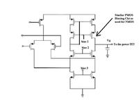
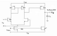
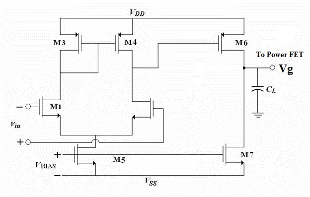
So you may shift your architecture to a fully cascode architecture Pic 1 or Two stage amp Pic 2

Pic 1:


Pic 2:


Pros & Cons:
Pic 1: Will give you high gain , single pole (ensuring max two poles in the over all LDO loop) good fro stability. The other pole is from the load cap CL (at LDO output). But output swing might not be enough to drive the Power FET Mp and biasing need extra ckt.

Pic 2: Will give you high gain, good output swing to drive your Power FET Mp. Easy to bias. But this architecture already is a two pole system so in the over all LDO loop you will see atleast 3 poles. The third pole is from the load cap CL (at LDO output). So you will have to think of proper compensation.

One more important thing..... Even if you are getting only 40dB from the error amp, if you manage to get enough gain from the Power FET then the loop gain A-beta might be 60dB. (Finally loop gain is what will matter ... and not the individual contributors in the loop). Generally Power FET will have to support high current .... so it will have a big size. Good for Gain if you can ensure that your PFET remains in saturation for all load current variations. Let us know your observation.

Hope this will help .... :)
 
Hi.
This is my circuit with node voltages.
I drew the circuit as tompham's but all transistors except M12 are in subthreshold. M12 is in linear.

Hi,

the common mode ranges for your op-amp is different so your op-amp acts like an comparator.. and gives Zero output..

so that your moses are out of region..

it is important to set a exact common mode then make the device sizes to get good biasing..

thanks..
 
  • Like
Reactions: anhnha

    anhnha

    Points: 2
    Helpful Answer Positive Rating
Thank you, SH and kenambo.

I replaced the load by a cascode current mirror and my gain now is 56dB. I am wondering why it is still low. I read somewhere that it should be about 90dB.
 

Hi, SH.
In your second picture, the signal is inverted. I think we need another stage to make the signal invert again.
Is that right?
What is the problem with that?
8993469100_1396692023.jpg
 

Thank you, SH and kenambo.

I replaced the load by a cascode current mirror and my gain now is 56dB. I am wondering why it is still low. I read somewhere that it should be about 90dB.

Hi..
folded cascode current mirror can give more gain.. you have to take some care while designing it..

for example.. the current in the current mirror decides the gain.. since

Id is directly proportional to gain.. try to increase the current of the current mirror..
and also try the last CS(pmos) Stage to get good gain..

thanks

- - - Updated - - -

- - - Updated - - -

Hi, SH.
In your second picture, the signal is inverted. I think we need another stage to make the signal invert again.
Is that right?
What is the problem with that?
8993469100_1396692023.jpg

hi..

i think the positions of inverting and non inverting terminal is interchanged...

because non-inverting terminal is the one which gives the bias for current mirror load..

and non inverting terminal is the one where we obtain the output..

so just change the polarity instead of adding another stage..

this will give you the correct result...
thanks
 

Hi Anhnha,

Hi, SH.
In your second picture, the signal is inverted. I think we need another stage to make the signal invert again.
Is that right?
What is the problem with that?

The picture is perfect .... Just check the phase at output. If the input at the negative terminal increases the output decreases ....and if the input at the positive terminal increases the output increases .... so it is fine ...
Fr your LDO you just ensure that the VFB (the feed back net) is connected to that terminal of the amplifier for which the over all phase in the LDO loop is 180deg (to ensure negative feedback) ....so donot change the polarity .... or else your loop will become a positive feedback ...

- - - Updated - - -

Hi kenambo,

hi..
i think the positions of inverting and non inverting terminal is interchanged...
because non-inverting terminal is the one which gives the bias for current mirror load..
and non inverting terminal is the one where we obtain the output..
so just change the polarity instead of adding another stage..
this will give you the correct result...

No .... terminals are not named on the basis of what load they have .... rather they are named on the basis of their impact on the output .... A terminal is negative if increase in voltage at that terminal causes the output to decrease ... and a terminal is positive if an increase in voltage causes the output to increase .... Its just the phase relation between the input terminal & output terminal that give the name ....

If I had a single stage differential amplifier (say upto the output of the 1st stage) then the terminal name would be reversed. Now addition of the 2nd stage shifts the overall phase by another 180 degs. Therefore in order to maintain the proper naming .. the names have to be reversed again .... So the terminal name in the picture is fine ....
 

I agree with SIDDHARTHA HAZRA, the terminal name in the picture are just fine.
 

Status
Not open for further replies.

Part and Inventory Search

Welcome to EDABoard.com

Sponsor

Back
Top