Continue to Site

Welcome to EDAboard.com

Welcome to our site! EDAboard.com is an international Electronics Discussion Forum focused on EDA software, circuits, schematics, books, theory, papers, asic, pld, 8051, DSP, Network, RF, Analog Design, PCB, Service Manuals... and a whole lot more! To participate you need to register. Registration is free. Click here to register now.

How Measure Telephone line voltage with mcu

Status
Not open for further replies.
you say amplifying it is making more complicated?
what is your proposal then ?

direct measurement of voltage with ADC?
 
Last edited:

at 6mohm it will draw around 8uAmp's i thought it would be low enough to be safe
There are standards for analog telephone terminal equipment. General rules and many national addenda.

For the ETSI domain, see EN 300 001

Generally, up to 50 µA DC line-to-line current in on-hook state is usually permitted for mains powered terminal equipment, even more (e.g. 0.5 mA) for line powered devices.

Line-to-earth insulation resistance must be in a high MOhm range, so true galvanic isolation is usually required.
 

Hi,
direct measurement of voltage with ADC?
--> yes.

On one side there are the two telephone lines, on the other side any device that can detect the voltage (optocoupler, bjt, fet, ADC)
But inbetween I see only two resistors for each telephone line.

****
Galvanic isolation:
so true galvanic isolation is usually required.
Isolation against what?
* against earth: yes. But the power supply is sayed to be independent. So isn't it independent = isolated from earth? Like a battery?
* against independent power supply? No. As long as "independent" means the powersupply provides the isolation to earth.
* against human touch? Yes. Put it in a plastic box.
* if you need signal connection to other circuitry (never mentioned): yes. Relay, optocoupler...if there are connections, then mainly they are "digital values". This means the isolation is way more simple than isolating analog signal between telephone lines and ADC.

--> i really don't see the need for the isolation on the analg side. Keep it simple.

Maybe more informations about your application, connections, signals, power supply can clarify the situation.

Klaus
 

Galvanic isolation:

Isolation against what?


Maybe more informations about your application, connections, signals, power supply can clarify the situation.

Klaus
hi, and thanx for your time :)

the circuit going to be powered from external source e.g AlarmPanel, PC, PABX these systems have powersupply and its negative maybe or maybe not be connected to earth
my worries was if my circuit will affect telephone line and that and only ! not worrying about "rest of circuits" i think its clear.

therefore i believe that in "Safe" enough to go with the ohm measurement !
 

Hi

continued to this issue, i have done many test's however it seems that i fail to understant how to isolate telephone line from my circuit

simple test
i have done a voltage divider 10Mohm-100K-100K-10Moh
across 200K i read with multimeter 0.45Volt on-hook , 0.10 off-hook
that's the same measurement to any telephone line company measurements

if i try to connect ground to any part of my circuit, voltage across divider changes, and values between line providers change too (read 0.21 on-hook and 0.46 off-hook to another telco)

if i try to connect divider to a differential opamp (eg ca3140) again reading's change and change between telco's too


to my understanting it is needed isolation
any idea what i am doing wrong and/or how to read diveder values wihere they are floating ?
 

If you take earth soil ground as 0V, then the telephone line is negative voltage. This makes it necessary for us to think through what we are doing. How does your device take a measurement?

the circuit going to be powered from external source e.g AlarmPanel, PC, PABX these systems have powersupply and its negative maybe or maybe not be connected to earth

This sounds as though your device has its ground at earth soil ground, correct? Does it have a positive supply? If so then it is unable to take readings of a negative voltage.

- - - Updated - - -

In the US, that is. Telephone line is -50 or -60V.
 

in US AND Europe its tip=0 ring =-48 on-hook and -20, -28 off-hook


that bring me back to 0 since , original question "how to measure telephone line without affecting it" grrr
 

Hi,

that bring me back to 0 since , original question "how to measure telephone line without affecting it" grrr

Did you use a DVM?
If not, then try it.
Did it affect telephone function?
If it did not affect the function, then use the same technique.
--> high ohmic direct voltage measurement with an ADC.

I already recommended this.

Did you test it?

Like a DVM you need an isolated plastic box for "your measurement device".

Klaus
 

yes i did, yes handheld DVM do not affect it

however afaik ADC measure's voltages from its ground to a value
but as i said "my measuring device" will/must be powered from a power source (12volt)
and as long as i connect ANY wall powered PSU , measurements change

even handheld DVM measures diffirent voltages at the same point's before ground is connected
 

Hi,

however afaik ADC measure's voltages from its ground to a value
Dont mix GROUND with EARTH POTENTIAL.

A DVM inside ADC and your device ADC is usually very similar. Both need to take care about their system ground.
But this has nothing to do with earth potential.
So if you assume your "measuremetn device" is a handheld one and it is battery powered it is obvious.

Now you say it is powered by a wall wart.
But all wall warts need to isolate output voltage from input voltage.
Often there is capacitive coupling between input and output, but the current is limited to a safe value. Nothing that may hurt you.

There is a little chance that your power supply output is referenced to earth potential (then it needs a 3 pin mains connector). --> Don´t use it. This won´t work. You can measure it with an ohmmeter.

The capacitve coupling typically is larger with modern switch mode wall warts.
If you want low capacitive coupling you may
* use regular low frequency transformer wall wart (no switch mode)
* use a switch mode wall wart with approval for medicine devices (some of them are cheap also)
* use a DCDC module inside your measurement device for a second isolation between input and output.

****
even handheld DVM measures diffirent voltages at the same point's before ground is connected
True for EARTH GROUND. But not true for your isolated system ground of your measurement device.

Klaus
 

i can not be sure where it will be power from

maybe would need a external psu maybe connected direct to ground !
therefore if i understand correct "direct measurement" is not correct to my case ?

is there any idea for isolation voltage from telephone line ? i see most systems use opto's
is there any circuit / idea/tutorial on this?
 

in US AND Europe its tip=0 ring =-48 on-hook and -20, -28 off-hook

Both the lines (there are two lines in most common telephones) are symmetrical; you can interchange the two and the phone will function exactly as before.

It is meaningless to mention the sign because only the difference is meaningful.
 

Hi,

maybe would need a external psu maybe connected direct to ground !
therefore if i understand correct "direct measurement" is not correct to my case ?
I don't understand.

What's wrong with a DCDC converter?

Maybe a picture could help.

Klaus
 

the only wrong is that it did NOT work,

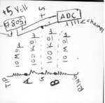
Here is a quick schematic

as long as point G connected to negative of 7805. Value measurement with handheld DVM, between points G<->B, changes.
Furthermore different values exist if i connect my circuit to telephone company A FXS than telephone company B FXS

handheld DVM reads the SAME values between all telco's as long as point G (neither B) in NOT connected to 7805


1.jpg

if i use an battery and NOT 7805/wall plug PSU , i get similar values between telco's and grounding changes NOT values
 
Last edited:

Hi,

You need to connect "A" with an ADC channel for differential measurement referred to "B".

Your ADC needs to be able to measure positive and negative input voltages. Referenced to GND as well as referenced to the other channel.

And you may need a capacitor parallel to both 100k to generate a LPF.

Klaus
 

As someone who spent years designing line testing equipment AND phone testing equipment for many Telco, I find this thread quite amusing. It suggests the problem is difficult when it it nothing more than an isolated voltage measurement.

1. Forget the polarity - measure the voltage after a bridge rectifier, a telephone contains a bridge rectifier for exactly the same reason.
2. Connect the 0V rail (NOT Earth ground) to the negative side of the bridge.
3. Connect the positive side of the bridge to a potential divider to drop the highest anticipated line voltage, including ringing voltage peaks, down to the ADC range using high value resistors.
4. Use a high impedance buffer (unity gain op-amp) to prevent the ADC loading the potential divider and to give it better current compliance.
5. Measure the voltage.

The important factors are:
Not to draw excessive current from across the wires
Not to draw current from either wire to Earth

The simplest way to prevent current to Earth is to use an isolated PSU for the measurement system.

If you absolutely must have a ground connection, use the bridge and potential divider then measure the differential voltage using an op-amp capable of very high input pin voltages such as the INA117.

Brian.
 

Hi,

It suggests the problem is difficult when it it nothing more than an isolated voltage measurement.
I fully agree.
What I wanted to say in all my postings is: It is far more easy to put the isolation on the power supply side than to isolate the analog signals.

1. Forget the polarity - measure the voltage after a bridge rectifier, a telephone contains a bridge rectifier for exactly the same reason.
I made my apprenticeship at the german telekom. But that was many years ago. So I can´t say that I´m that experienced with nowadays telco technique.

Just from the measurement side: I like to measure the pure signals. With this the software is able to measure/calculate everything very flexible.

For sure it may be more effort to write the software to divide DC voltage from AC voltage or calculate the true RMS voltage of the ringing signal without influence of a DC signal .. and so on.
With a rectifier in the analog path.. it somehow limits the possible calculations.

It´s my personal taste: I like to program those digital stuff like: filters, true RMS, DFT, correlation, FFT, regulation loops, ...

In the end there is no complete right or wrong. There are many ways.

Klaus
 

Most modern phones have line connection s like this:
incoming line -------> filter/protection components --> bridge ---> hook switch and 'bleed' path of a few uA to keep electronics alive.
&
incoming line ------->DC blocking capacitor --> bi-directional voltage drop (diac or back to back Zeners) --> bridge --> ringer circuit

The voltage drop is to prevent line noise and maybe audio reaching the ringer circuit, it is typically a pair of 3.3V Zeners back to back to set a minimum threshold before any signal can 'tinkle' the ringer.

The bridge rectifier in the hookswitch path is just to ensure the phone sees the same polarity if the line is reversed. The one in the ringer path is to convert the AC ringing voltage to a supply for the ringer oscillator.

Note that most Telco systems these days have a facility to briefly (~100mS) reverse the line voltage to alert 'intelligent' phones that a burst of data is about to be sent using FSK. It takes the modem out of standby to receive things like caller ID information or to automatically update the time/date display. When measuring line voltage it is important to factor the reversal in the design.

Brian.
 

HI first thank's all for your time

to sum , the circuit is going to be powered from external PSU (12volt) that psu maybe or maybe not have 0v=gnd and i do not know it !

1. Forget the polarity - measure the voltage after a bridge rectifier, a telephone contains a bridge rectifier for exactly the same reason.
2. Connect the 0V rail (NOT Earth ground) to the negative side of the bridge.
3. Connect the positive side of the bridge to a potential divider to drop the highest anticipated line voltage, including ringing voltage peaks, down to the ADC range using high value resistors.
4. Use a high impedance buffer (unity gain op-amp) to prevent the ADC loading the potential divider and to give it better current compliance.
5. Measure the voltage.

The simplest way to prevent current to Earth is to use an isolated PSU for the measurement system.

If you absolutely must have a ground connection, use the bridge and potential divider then measure the differential voltage using an op-amp capable of very high input pin voltages such as the INA117.

Brian.

1) i do will use bridge on final project for sure .. now test !
2) 0V ? for example 0v of 7805 ? that rail maybe connected to
3) always did that way (high ohm resistor divider)
4) i am trying but seems i fail :) , my problem persist on on the fact that unit gain buffers (f.e. CA3140) have negative supply =0V = GND and that's mess up measuments
5) offcourse what else ?!


Hi,

I fully agree.
What I wanted to say in all my postings is: It is far more easy to put the isolation on the power supply side than to isolate the analog signals.

Klaus


can you please suggest a "isolated dc/dc" as you suggest ? isn;t 7805 is one of these?

thanx
 

Hi,

One of many... just as an example:
Aimtec AM1D-1212.

Klaus
 

Status
Not open for further replies.

Similar threads

Part and Inventory Search

Welcome to EDABoard.com

Sponsor

Back
Top