Continue to Site

Welcome to EDAboard.com

Welcome to our site! EDAboard.com is an international Electronics Discussion Forum focused on EDA software, circuits, schematics, books, theory, papers, asic, pld, 8051, DSP, Network, RF, Analog Design, PCB, Service Manuals... and a whole lot more! To participate you need to register. Registration is free. Click here to register now.

How can I reduce voltage on a battery.

watersteps

Newbie level 4
Joined
Jun 15, 2010
Messages
7
Helped
0
Reputation
0
Reaction score
0
Trophy points
1,281
Location
York, Pa
Activity points
1,350
I have a 24 volt dc battery that I want to use on an 18 and 20 volt tool. I have built an adapter to mount the 20 volt tool to the battery. When I mount the tool on the adapter and then on the 24 volt battery nothing happens. Well the light on the tool goes out when I pull the trigger.
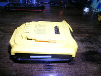
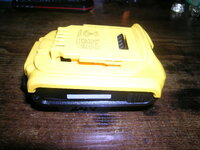
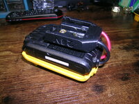
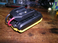
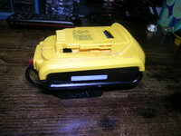
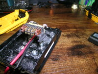
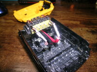
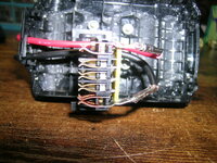
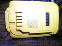
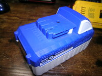
Lets go back to the beginning, I have several 24 volt SunJoe and SunSnow batteries, I also have several 10 and 20 volt DeWalt power tools that I could use extra batteries for. No one that I know of makes an adapter for this use. So I built an adapter out of a 2amphour Dewalt battery by removing the batteries and charging electronics board. I purchased a DIY adapter for the SunJoe 24 volt battery. This adapter is bolted to the 2amphour battery casing and wired the positive and negative wires from the DIY adapter to the connections in the 2 amphour adapter.
I have been told that if the DeWalt tools were brush type tools this would work fine, but they are not brush type tools. So, can I install a voltage regulator to reduce the voltage from 24 to 20 and maybe even 18 volts??
I have attached some pictures to help explain what I am doing.
--- Updated ---

I will add this info that may help find an answer. I have an adapter from DeWalt that allows me to use 20 volt batteries on 18 volt tools. The adapter works just fine. I opened this adapter up and find a small electronics board with these items mounted to it. One small round can with 100-35v-VT printed on it and another small can with 220-16v-VT printed on it, a small coil of copper wire with 220 printed on it. It also has a usb connection on the board.
 

Attachments

  • DSCN9162.JPG
    DSCN9162.JPG
    912.8 KB · Views: 47
  • DSCN9163.JPG
    DSCN9163.JPG
    873.8 KB · Views: 49
  • DSCN9166.JPG
    DSCN9166.JPG
    1 MB · Views: 51
  • DSCN9167.JPG
    DSCN9167.JPG
    1 MB · Views: 52
  • DSCN9168.JPG
    DSCN9168.JPG
    950.4 KB · Views: 51
  • DSCN9169.JPG
    DSCN9169.JPG
    1 MB · Views: 51
  • DSCN9170.JPG
    DSCN9170.JPG
    996.5 KB · Views: 49
  • DSCN9171.JPG
    DSCN9171.JPG
    1,012.6 KB · Views: 50
  • DSCN9172.JPG
    DSCN9172.JPG
    837.9 KB · Views: 51
  • DSCN9173.JPG
    DSCN9173.JPG
    963 KB · Views: 51
Last edited:
Can you draw a block diagram of the wires and voltages, where the caps are, with load & battery connections?
Or is that mainly for USB?

It's hard to make a 10V high current power supply cool for a 10V motor that draws 10x the current on surge full power from stop from a 24V battery, but I'll try.
It's basically around a 100W 10A, 10V power supply or more.

That's why nobody makes them.
 
I believe these items are for the USB, but something in this set up reduces the 20 volts to 18 volts. I will try to make a line drawing. Someone makes an adapter for 24 volt Kobalt batteries so they can be used with 20 volt tools but this will not fit the DeWalt tools.
 
Hi,

the headline is misleading:
"How can I reduce voltage on a battery."
If you want to reduce the battery voltage .. you had to discharge it.

****
So you rather want to convert the nominal 24V battery voltage down to 18V or 20V to supply your tool.
It is called step down converter, or buck converter.
To specifiy a buck converter you need at least:
* input voltage min
* input voltage max
* output voltage
* output current

Input voltage min and max are very important. Because a 24V battery can be down to let´s say 20V and up to 29V... depending on battery type.

***
But then you say you have a converter doing exactly this .. and it works fine.
--> so what´s the problem then?

****
Your desription of the parts ... is
* on the one side so coarse that we don´t know whether its a big capacitor or a tiny 5 pin IC
* on the other hand ... I don´t know what the information is good for.
Let´s say we have a clear description that one is a BUZ44 MOSFET. What then? We don´t know whether you want to test it, replace it, remove it ....

***
My recommendantion:
Focus on one single problem. Give all related informations. Ask a detailed question.

Klaus
 
OK I checked the 20 volt to 18 volt adapter that works on the 18 volt tool with a 20 volt battery. There are 2 14 ga wires that go from the 20 volt battery to the 18 volt tool. There is nothing in either wire like a diode or a resistor. There are 2 20ga wires that go to a USB connection.
It seems like the 20 volt power will not harm the 18 volt tool. But when I supply 24 volts to a 20 volt tool it will not work.
I did find an adapter for a 24 volt Kobalt battery that works with a 20 volt DeWalt tool. So there must be something in this adapter that reduces the the 24 volts to 20 volts. This is what I need to use the 24 volt SunJoe battery with my 20 volt DeWalt tools. The Kobalt adapter costs $30.00 and I may need to buy one just to find out what is in the the adapter that allows for the 24 to 20 reduction.
 
the light on the tool goes out when I pull the trigger.
Is it because the battery fails immediately? Or is it because the tool only accepts up to a certain voltage?

Assuming it's the latter...
Have you tried dropping battery voltage a few volts artificially as you switch on the tool? A few diodes in series is the obvious way to do this. Say 4 diodes rated for 10 Amperes. However this method of resistive drop wastes a few tens of Watts as heat.
So...
Battery voltage drops as soon as you draw current. Perhaps you need not lose several Watts as heat. As soon as the tool starts running eliminate (bypass) the diodes from the current path using a heavy-duty switch. Battery voltage remains in the operational range. However it's cumbersome to press switches quickly every time you turn it on.

A series inductor can slow the rise of voltage as the motor turns on. Say 1/3 Henry taking half a second to get the motor up to speed. The inductor should be able to carry several Amperes. Or an inductor charging a capacitor. This topology requires experimentation and safeguards against hi-voltage spikes.

As for cracking open every battery case, disassembling the battery pack and removing one or more cells. Theoretically the easy solution, but many opportunities for self-injury. It's sensible to avoid this.
 
I do not want to harm the 24 volt batteries as I still use them for the lawn mower, snow blower and other tools. Can I just put 4 or 5 diodes in the positive wire inside the adapter I built?
 
Could I use a Buck Converter DC Voltage Regulator? I would need one that can handle 24 volts DC input and 20 volts DC output. I saw some that were adjustable, but I don't know which one to purchase.
 
Well I want to thank everyone that tried to help me and even the one person who said I listed this request wrong and that I have "course" descriptions of the electronics I have. Well that is why I came to this forum, to find out what I need to know.
When young and old people come to me for advise on how to rebuild engines, transmissions, rear ends and all things mechanical, I at least try to understand that they don't know anything about the item they want to repair. Then I talk with them and help them work out the problem.
I will try to find answers to my questions elsewhere.
Thanks Again
 
The point is that no one can tell you "what you need to know" if you can't present what your actual problem is. You mis-stated your purpose right in the headline and went downhill from there. You say you have built some kind of mythical adapter, provide no schematic, and then you want to know 'why your light goes out when you pull the trigger'.

You also say you took a battery, removed the battery and it's charging board, then took a "DIY" adapter and connected it to a "2amphour adapter". Do you mean the 2 amp-hour battery case? It's pretty difficult to follow what you're talking about. You don't even give us a clue about this "DIY adapter".

I thought that perhaps the problem here was that English was not your first language, but I see you're from Pennsylvania, so that's not the reason. The people on this board are extremely knowledgeable and helpful. Don't blame them because that can't solve your poorly stated problem.

P.S. the word is "coarse" not "course".
 
First there is no problem! It is simple I want to take a 24 volt dc battery and use it to power a 20 volt dc tool. I attached pictures of the 2amphour casing and the DIY adapter attached to it, what more do you want? Some how I need to lower the 24 volts that come out of the battery to 20 volts to power the tool.
A person that does not know anything about electronics is asking for help, and you guys just make an xxx out of them. And I never asked why the light went out I just stated it did.
Since this was so hard for you guys, I went to ebay and found the answer in less then an hour, and no one even cared that I am electronically uneducated.
 
Could I use a Buck Converter DC Voltage Regulator? I would need one that can handle 24 volts DC input and 20 volts DC output. I saw some that were adjustable, but I don't know which one to purchase.
Yes, but its transient response might be a factor on startup behaviour.

Regards, Dana.
--- Updated ---

I do not want to harm the 24 volt batteries as I still use them for the lawn mower, snow blower and other tools. Can I just put 4 or 5 diodes in the positive wire inside the adapter I built?
Yes or a power Zener or a power zener substitute circuit :


Note all these waste energy, not very green.....


Regards, Dana.
 
We don't know if the power tool needs an immediate huge current surge at startup, or whether it has a speed switch that lets you start slowly at low current and rev it up.

Evidently it needs 18 or 20V to work in the first place. A battery pack is excellent to supply motors because it's flexible in the way it provides high current quickly when demand goes up. It makes the tool predictable to use.

The buck converter is a limiting influence in the current path. Action becomes somewhat unpredictable. Anyway this simulation is a buck converter that steps down 24V to 20V 4 Amperes, upwards of 100W. (At left apply whatever voltage you wish as a reference.) Output voltage remains at 20V when the load is absent (off).

buck converter 24V op amp PNP to 20V 4A.png


Below is link that runs above schematic. Opens falstad.com/circuit. Loads schematic into animated interactive simulator. Runs it on your computer.

tinyurl.com/yklxvzmy

Toggle Full Screen (under File menu).
Op amp may be unable to provide enough current to drive transistor. Further design effort is needed.
 
Hello,

Thanks for blaming it on us!
Btw: English is not my first language. I´ve been taught in school. Almost zero experience in speaking.

***
So let´s review: In post#4 I wrote:
So you rather want to convert the nominal 24V battery voltage down to 18V or 20V to supply your tool.
It is called step down converter, or buck converter.
To specifiy a buck converter you need at least:
* input voltage min
* input voltage max
* output voltage
* output current

Input voltage min and max are very important. Because a 24V battery can be down to let´s say 20V and up to 29V... depending on battery type.
Did you ever gave a meaningful feedback on this? No!

Later in post#8 you asked
Could I use a Buck Converter DC Voltage Regulator?
What? I´ve already told you! See above! And I´ve told you what data to look for!

*****
It seems you are more a mechanics guy:
So imagine some guy comes to you and asks for a lost thing that is used to keep two metal sheets together.
You tell him it is called "bolt" and you also tell him that he needs to know: head type, thread type, length, diameter...
He tells you a big story about sheet color, sheet length, that the one sheet is of this material, today it´s windy ... but zero feedback about what you said is important.

But later asks if he could use a bolt. !!?? and again: he needs it for two metal sheets.
And even later he blames you for not being helpful and he found the solution on ebay. Would you feel guilty?

Not able to articulate in a way that people with same mother tongue understand ... I can´t imagine how you would perform in a foreign language.
People asking for help in this forum don´t need to be electronics experts. But they need to able to communicate, to take place in the conversation, to read what people have written, to respond to them. They need be able to focus on the posts, tell what they understand so far and where they need additional information.

***********

In post#3 you wrote:
I will try to make a line drawing.
I guess you will blame it on us that nobody told you to show us this drawing...

***************

From post#6
A few diodes in series is the obvious way to do this. Say 4 diodes

your response:
Can I just put 4 or 5 diodes in the positive wire inside the adapter I built?
So what is the question here ... that is not already answered in the post above?

We: the obvious way is to use a bolt.
You: can I use a bolt to tighten two metal sheets?

The whole thread is like this...

Klaus
 
"go to ebay and found the answer in less then an hour,"

Trust me the converter will never be as good as a battery for reasons I already stated. Something will be compromised, but if you don't need max power or a reliable tool, use it. Ebay is littered with junk solutions.

Surge current or max starting torque is 10x rated current, which means it would be too expensive to support > 1kW power supply, yet the battery can supply surge power.

If you have variable speed, just use the 20V and cut back max available power by 30%, or use it for as long as it lasts and then upgrade to a 24V tool.
 

LaTeX Commands Quick-Menu:

Part and Inventory Search

Welcome to EDABoard.com

Sponsor

Back
Top