Continue to Site

Welcome to EDAboard.com

Welcome to our site! EDAboard.com is an international Electronics Discussion Forum focused on EDA software, circuits, schematics, books, theory, papers, asic, pld, 8051, DSP, Network, RF, Analog Design, PCB, Service Manuals... and a whole lot more! To participate you need to register. Registration is free. Click here to register now.

How can I convert a square wave output to a nearly sine wave output?

Status
Not open for further replies.
Yes, it's quite easy.
I would recommend using a Wien bridge oscillator. You can find many examples on the web, using a variety of amplitude stabilising methods. I suggest you have a search so you can decide which method you want to use.

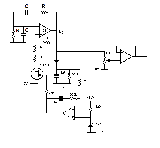
Here's one version which I designed. The amplitude control may be rather more complicated than you want, but it works well.


Wienosc2.gif


The frequency of a Wien oscillator is given by the following equation

Wienfrequency.gif


A value of 120k for the two Rs and 27nF for the two Cs give a calculated frequency of 49Hz. You may have to make small adjustments, as necessary, to get the frequency exact - if it's important.

___________________________________________________________________________________


I used the same method which you mentioned to make a 50Hz 220V power supply for my record turntable when I was living in South America, where the local mains was about 60Hz and somewhere around 110V. Neither of those figures being reliable. I did actually start with a special chip which gave a precise 50Hz out. It was derived from a crystal oscillator with a suitable dividers in the chip. The output was a square wave, which I passed through a band pass filter.
The sine wave drove a 4 -5 watt amplifer which had a reversed mains transformer at its output.
I don't think the chip is manufactured any more. But that's irrelevant

Thank you very much for the design, sir. I am sorry to say that due to my lack of knowledge in this field, I can't understand where the output comes out. Also I am unsure about the IC. I shall be very grateful if you kindly elaborate. Thank you sir.

---------- Post added at 14:56 ---------- Previous post was at 14:52 ----------

Dear baghu
Hi
I'm agree with syncopator . it seems good way .
There are many many ways to obtain your aim .
If you tell me a bit more explanation , that how much quality , and price do you want , i can suggest you best way to achieve your purpose .
You can use linear ways , or switch mode ways . both of them are easy , but at switch mode , systems , you'll be able to decrease the price and increase the quality .
BTW : one of simple ways , that you can do is royer oscillator ( but it's out pu is square wave ) . and it is not good way for you , i think.
if you need powers up to some KW , the switch mode ways are best choices ( as you told , you want 50 W , but if you want more powers , no problem )
And you can do it with your self
All the best
Goldsmith
Hi,
Good afternoon.
Many thanks for your response Ali. Yes I need a linear inverter. Load is maximum 50watts. Thanks a lot.

---------- Post added at 14:59 ---------- Previous post was at 14:56 ----------

I posted a slightly simpler circuit not so long ago. The sine wave will not be quite as pure as the JFET controlled version.

https://www.edaboard.com/threads/241017/#post1032292

Keith.

Thank youfor the thread, Keith. What frequency of approximate sinewave does this circuit generate? What amplifier do I need? Thanks.
 

Again Hi
If you want linear ways , the way that Syncopator introduced is good way that you can follow it .
Best Wishes
Goldsmith
 

Thank youfor the thread, Keith. What frequency of approximate sinewave does this circuit generate? What amplifier do I need? Thanks.

The values shown give 15kHz. The opamp used there is the TL072 but others could be used.

Keith.
 

I am sorry to say that ... , I can't understand where the output comes out. Also I am unsure about the IC. I shall be very grateful if you kindly elaborate.
The i.c. at the top is the oscillator. The one beneath it is part of the amplitude control. The output from the oscillator is buffered by the voltage follower at the right hand side. It has a potentiomoter at its input so that the amplitude applied to the subsequent circuit/s may be adjusted as desired.

I tried three types of i.c., LF351, TL071 and 5534, simply because I had them among my components. They all worked satisfactorily. More or less any commonly available op-amp will work too.


Many thanks for your design. Tons of thanks to all who have shared their knowledge with me. I am starting this project soon. Thank you very much to you all. May the Almighty bless you all. :)
 

Status
Not open for further replies.

Part and Inventory Search

Welcome to EDABoard.com

Sponsor

Back
Top