internetuser2k12
Banned

No when you define DATA_PORT PORTA you are actually setting the whole port and if you write 0xff to DATA_PORT then RA6 and RA7 i.e., RS and E becomes 1.
Follow along with the video below to see how to install our site as a web app on your home screen.
Note: This feature may not be available in some browsers.

When i change thisput urls in url tags and not code tags.
Datasheet says it uses KS0066 controller. I don't know wheather it is compatible with HD44780 controller or not. I have to check.
On the net it is mentioned that KS0066 is compatible with HD44780 controller.
SetAddr (0x80); and SetAddr (0xC0); is right for Row1 and Row2. I checked about it.
Can you post your LCD connection circuit?
Try this code
Code:void WriteString(char *buffer) { while(*buffer) // Write data to LCD up to null { Delay20TCY(); WriteChar( *buffer); // Write character to LCD buffer++; // Increment buffer } return; } void WriteChar(char data) { DATA_PORT &= 0xf0; DATA_PORT |= ((data>>4)&0x0f); RS_PIN = 1; // Set control bits Delay20TCY(); E_PIN = 1; // Clock nibble into LCD Delay20TCY(); E_PIN = 0; DATA_PORT &= 0xf0; // Lower nibble interface DATA_PORT |= (data&0x0f); Delay20TCY(); E_PIN = 1; // Clock nibble into LCD Delay20TCY(); E_PIN = 0; }
Change thistoCode:#define DATA_PORT PORTA #define RS_PIN PORTAbits.RA6 #define E_PIN PORTAbits.RA7Code:#define DATA_PORT LATA #define RS_PIN LATAbits.RA6 #define E_PIN LATAbits.RA7
#define RS_PIN     	LATAbits.RA6
#define E_PIN LATAbits.RA7#define RS_PIN LATAbits.LATA6
#define E_PIN LATAbits.LATA7Thank you for the datasheet.Datasheet of KS0066 if you need http://www.cs.washington.edu/educa...Projects/LakeMan/adv/datasheets/char_lcd.pdf
- - - Updated - - -
Change it toCode:#define RS_PIN LATAbits.LATA6 #define E_PIN LATAbits.LATA7
Then why you don't increase the delays? Insert big delays whether this is the problem or not, and when you find the solution restore proper delay values.I dont know, but i think the problem is with the delays.
The delays for pic18f2520 is much faster than those who did the pic18f1220.
void main (void)
{
//SET UP
// OSCCON defaults to 31kHz. So no need to alter it.
ADCON1 = 0x0F;
CMCON = 0x07;
CVRCONbits.CVROE = 0;
TRISA = 0b00100000;;	//sets PORTA
PORTA = 0b00000000;	//turns off PORTA outputs
// this code configures the display
WriteCmd ( 0x02 );				// sets 4bit operation
WriteCmd ( FOUR_BIT & LINES_5X7 );	// sets 5x7 font and multiline operation.
WriteCmd ( CURSOR_BLINK );			// blinks cursor
WriteCmd ( CURSOR_RIGHT  );			// moves cursor right
// Start of user program.
SetAddr (0x80);
WriteString("Hello World");
Delay1KTCYx(8); //delay 1s
WriteCmd(CLEAR_SCREEN);
SetAddr (0xC0);
WriteString("Hello again");
while(1);
}#include <p18f2520.h>
#pragma config WDT=OFF , OSC=INTIO67 , PWRT = ON, LVP=OFF, MCLRE = OFF
#include <delays.h>
#define CLEAR_SCREEN 0b00000001
#define FOUR_BIT 0b00101100
#define LINES_5X7 0b00111000
#define CURSOR_BLINK 0b00001111
#define CURSOR_RIGHT 0b00000110
#define DATA_PORT LATA
#define RS_PIN LATCbits.LATC1
#define E_PIN LATCbits.LATC2
void Delay20TCY()	//20 clock cycles, 2.5mS
{
Delay10TCYx(2);
}
void SetAddr(unsigned char DDaddr)
{
DATA_PORT &= 0xf0; // Write upper nibble
DATA_PORT |= (((DDaddr | 0b10000000)>>4) & 0x0f);
RS_PIN = 0; // Set control bit
Delay20TCY();
E_PIN = 1; // Clock the cmd and address in
Delay20TCY();
E_PIN = 0;
DATA_PORT &= 0xf0; // Write lower nibble
DATA_PORT |= (DDaddr&0x0f);
Delay20TCY();
E_PIN = 1; // Clock the cmd and address in
Delay20TCY();
E_PIN = 0;
}
void WriteCmd(unsigned char cmd)
{
DATA_PORT &= 0xf0;
DATA_PORT |= (cmd>>4)&0x0f;
RS_PIN = 0; // Set control signals for command
Delay20TCY();
E_PIN = 1; // Clock command in
Delay20TCY();
E_PIN = 0;
// Lower nibble interface
DATA_PORT &= 0xf0;
DATA_PORT |= cmd&0x0f;
Delay20TCY();
E_PIN = 1; // Clock command in
Delay20TCY();
E_PIN = 0;
}
void WriteChar(char data)
{
DATA_PORT &= 0xf0;
DATA_PORT |= ((data>>4)&0x0f);
RS_PIN = 1; // Set control bits
Delay20TCY();
E_PIN = 1; // Clock nibble into LCD
Delay20TCY();
E_PIN = 0;
DATA_PORT &= 0xf0; // Lower nibble interface
DATA_PORT |= (data&0x0f);
Delay20TCY();
E_PIN = 1; // Clock nibble into LCD
Delay20TCY();
E_PIN = 0;
}
void WriteString(const rom char *buffer)
{
while(*buffer) // Write data to LCD up to null
{
Delay20TCY();
WriteChar( *buffer); // Write character to LCD
buffer++; // Increment buffer
}
return;
}
void main (void)
{
//SET UP
// OSCCON defaults to 31kHz. So no need to alter it.
ADCON1 = 0x0F;
CMCON = 0x07;
CVRCONbits.CVROE = 0;
TRISA =0b00000000; //sets PORTA
LATA = 0b00000000; //turns off PORTA outputs
TRISC =0b00000000; //sets PORTA 3
LATC = 0b00000000; //turns off PORTA outputs
// this code configures the display
WriteCmd ( 0x02 ); // sets 4bit operation
WriteCmd ( FOUR_BIT & LINES_5X7 ); // sets 5x7 font and multiline operation.
WriteCmd ( CURSOR_BLINK ); // blinks cursor
WriteCmd ( CURSOR_RIGHT ); // moves cursor right
// Start of user program.
SetAddr (0x80);
WriteString("Hello World");
Delay10KTCYx(100);
WriteCmd(CLEAR_SCREEN);
SetAddr (0xC0);
WriteString("Hello again");
while(1);
}My final code is the following:
The clock frequency is 40 MHzWhat is your clock frequency?
Yes i added delay before and after screen command and its working but alexx said that "This will not fix the problem, but it will help you understand what is going on, before the second print."Good that you problem got solved? Did you just add delay?
The initialize is it this one?:Again: :smile:
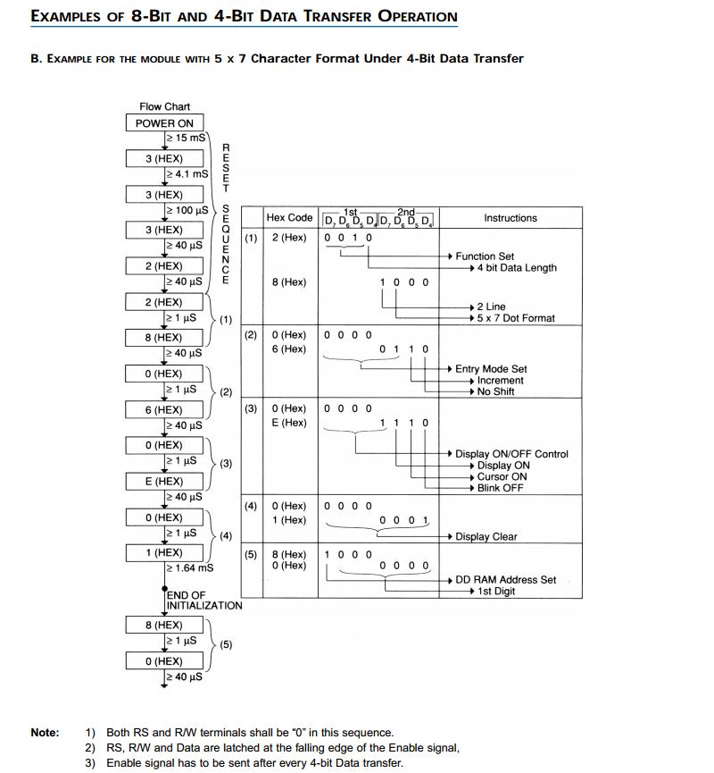
Before and after clear screen command add a delay over 1 sec to understand what is going on. Also fix the initialize sequence according to datasheet.

This is the initialization algorithm, 4 bit mode:The initialize is it this one?:
Yes i added delay before and after screen command and its working but alexx said that "This will not fix the problem, but it will help you understand what is going on, before the second print."
40MHz means 25ns. 25*20 = 500ns. This doesn't meet the requirement of 1.64ms. I'm not aware of PIC or the compiler you are using, but I believe that it is time you gave a second look into your delay functions.The clock frequency is 40 MHz
Code:void Delay20TCY() //20 clock cycles, 2.5mS
")
void Delay20TCY() //20 clock cycles, 2.5mS
{
Delay10TCYx(2);
}void Delay20TCY()
{
Delay10TCYx(50);
}