Continue to Site

Welcome to EDAboard.com

Welcome to our site! EDAboard.com is an international Electronics Discussion Forum focused on EDA software, circuits, schematics, books, theory, papers, asic, pld, 8051, DSP, Network, RF, Analog Design, PCB, Service Manuals... and a whole lot more! To participate you need to register. Registration is free. Click here to register now.

High Frequency using 8051

Status
Not open for further replies.
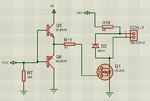
The schematic is OK although I would add a resistor in series with the input. Your problem is the 11N60DM2 which needs as much as 5V on its gate before it STARTS conducting. Ideally you want far more than that to ensure it turns full on .

The simplest modification I can think of is to connect Q5 collector and R2 to 24V and add another transistor at the input to drive Q5 and Q6.

Brian.

I have made a small testing.
i tried switching Mosfet ON and OFF after every delay of 2 seconds to check if i am getting the proper output.
but yes, i am getting the proper output of 24V and 0V after every 2 seconds. so why when i switch it faster at 300Khz, the mosfet is not getting OFF and stays ON due to which i am getting continues 24V at the output.
 

Both of those might work but they would be risky. You might find it works with one MOSFET but not another of the same type. You really need to increase the gate voltage or use a logic level MOSFET.

Try this simple change:
1. remove Q6.
2. connect Q5 emitter to ground,
3. connect Q5 collector to the gate of the MOSFET and a 1K resistor to +24V,
4. connect Q5 base to the 8051 through a 470 Ohm resistor.

The idea is that the 10K resistor holds the MOSFET in hard conduction, current through Q5 when biased from the 8051 pulls the gate voltage close to zero and turns it off.
Beware that if you stop the drive waveform or disconnect the 8051 it will leave the MOSFET in conducting state, if you want to protect against that without other side-effects, connect a 100K resistor from Q5 base to +24V.

Brian.
 

so why when i switch it faster at 300Khz, the mosfet is not getting OFF and stays ON due to which i am getting continues 24V at the output.
Try what I suggested.

Your problem with higher frequencies is you need more drive current and you are already borderline on having enough available. Don't think of a MOSFET as being a perfect voltage operated switch, it comes close at low frequencies but imagine there is quite a large capacitor between its gate and source pins (think 1nF or more). As the frequency increases, so does the current needed to charge and discharge that capacitance. This is why you usually see a power driver before the MOSFET and most of the common IR2xxx driver ICs are rated at 1A or more output current. It isn't because of the DC switching characteristics of the MOSFET, it is to charge and discharge the gate voltage rapidly to ensure full switching and least time in the partially conducting region where power loss is highest.

Brian.
 

Both of those might work but they would be risky. You might find it works with one MOSFET but not another of the same type. You really need to increase the gate voltage or use a logic level MOSFET.

Try this simple change:
1. remove Q6.
2. connect Q5 emitter to ground,
3. connect Q5 collector to the gate of the MOSFET and a 1K resistor to +24V,
4. connect Q5 base to the 8051 through a 470 Ohm resistor.

The idea is that the 10K resistor holds the MOSFET in hard conduction, current through Q5 when biased from the 8051 pulls the gate voltage close to zero and turns it off.
Beware that if you stop the drive waveform or disconnect the 8051 it will leave the MOSFET in conducting state, if you want to protect against that without other side-effects, connect a 100K resistor from Q5 base to +24V.

Brian.

I have even tried using logic level Mosfet, IRLZ44, but the things does not work.
i have changed the 10K base resistor to pull down from Pull up, the frequency now what i am getting is approx 50 Hz, quite low as per the expections.
Trying your recommened circuit, but for switching mosfets in high frequency, we need a push pull gate driver.

- - - Updated - - -

Let me make a point that all this results are without any load
 

Hi,

i am getting continues 24V at the output.

Let me make a point that all this results are without any load
Why without load, now? It's no surprise if you don't have a load ... to get continous straight line
The Mosfet pulls to one rail .... but nothing pulls to the other rail.

Klaus
 

24V Vgs is too much on most MOSFETS, they normally have a Vgs_max at 20v. (or less).
 

Try what I suggested.

Your problem with higher frequencies is you need more drive current and you are already borderline on having enough available. Don't think of a MOSFET as being a perfect voltage operated switch, it comes close at low frequencies but imagine there is quite a large capacitor between its gate and source pins (think 1nF or more). As the frequency increases, so does the current needed to charge and discharge that capacitance. This is why you usually see a power driver before the MOSFET and most of the common IR2xxx driver ICs are rated at 1A or more output current. It isn't because of the DC switching characteristics of the MOSFET, it is to charge and discharge the gate voltage rapidly to ensure full switching and least time in the partially conducting region where power loss is highest.

Brian.

I tried using both the circuits (Attached). But none of the circuits work. at gate pin of mosfet i am getting approx 17V in both the cases, and also the frequency of 333.Khz. but output of mosfet shows only 24V straight line.
also i tried using both the mosfets, IRLZ44 and also STP36NF06, but the result is the same
 

Attachments

  • High Frequency1.png
    High Frequency1.png
    17.6 KB · Views: 131
  • High Frequency.png
    High Frequency.png
    60.2 KB · Views: 157

All I can think of is you have the diode reversed or the coil has such low impedance it appears like a short circuit.

Can you describe the coil please.
Are those resistors really 46 Ohms, it isn't a standard value.

Brian.
 

Hi,

I can't see why the gate voltage should be 17V only.
Thus I assume the schematics don't show the reality.

Please take some photos of your circuit...including scope connections and ... show the scope pictures

Klaus
 

All I can think of is you have the diode reversed or the coil has such low impedance it appears like a short circuit.

Can you describe the coil please.
Are those resistors really 46 Ohms, it isn't a standard value.

Brian.

I have checked the diode, Anode to 24V and cathode to MOSFET Drain,
Sorry, the resistor is 47 Ohms.
I have not connected any coil, all the testings are made without load
 

Hi,

I can't see why the gate voltage should be 17V only.
Thus I assume the schematics don't show the reality.

Please take some photos of your circuit...including scope connections and ... show the scope pictures

Klaus

I have attached the circuit diagram with scope reading.
 

Attachments

  • High frequency Issue.jpg
    High frequency Issue.jpg
    450.7 KB · Views: 159

Something is wrong there.
I assume the top 'scope trace is gate to SOURCE not drain.
Can you show a photograph of the construction please, all I can think of is you have the source and gate pins swapped.
When you say "I have not connected any coil, all the testings are made without load" I assume you have SOME load on it, even if the coil pins are shorted together, otherwise there can be no drain current.

Brian.

Thank you to all...
as per the previous post of betwixt, i realized that the MOSFET wont give proper output without the load, Actually the problem was that there was no load attached.
i have attached the Resister of 47 Ohms 2 watts at 24V and Drain pin, received the exact frequency as required.
i am sorry, as i was not aware that MOSFETS do not work properly without load. I have attached the final circuit diagram for someone else reference facing the same issues.

- - - Updated - - -

Something is wrong there.
I assume the top 'scope trace is gate to SOURCE not drain.
Can you show a photograph of the construction please, all I can think of is you have the source and gate pins swapped.
When you say "I have not connected any coil, all the testings are made without load" I assume you have SOME load on it, even if the coil pins are shorted together, otherwise there can be no drain current.

Brian.

but now, i have one more question, actually i am going to use 21 swg copper insulated wire approx 100 70 to 80 feet length whoes resistance is around 14 ohms per 1000 feet.
so in my system when i attach 70 to 80 feet of wire, i will get the resistance of approx 1 ohms, which will short my circuit, so what precaution have to be taken for that.
 

Attachments

  • High Frequency.png
    High Frequency.png
    79.5 KB · Views: 128

Np precautions are necessary except for possibly radiating interference. The impedance of the 'coil' will be the load rather than its pure resistance. Presumably the coil is resonant and presents several Ohms impedance.

Brian.
 

Hi,

i was not aware that MOSFETS do not work properly without load.
It's not a problem of the MOSFET. It's the same as with BJTs and relays....

The MOSFET (or bjt or relay...) switches to GND, otherwise it is OPEN. The voltage when OPEN is undefined. Due to stray capacitance it stays at GND level (for a while). Thus you see 24V.

Klaus
 

With a max voltage of only 60V, I would try to avoid using IRFZ44N with an operating voltage of 24V DC.

Here's my sim of your circuit using 60KHz 50% pulses and it looks quite acceptable.

You can try with 300Khz and see if that works too...
 

Attachments

  • eda mosfet driver_1.PNG
    eda mosfet driver_1.PNG
    64.6 KB · Views: 120

Status
Not open for further replies.

Similar threads

Part and Inventory Search

Welcome to EDABoard.com

Sponsor

Back
Top