louarnold
Member level 2

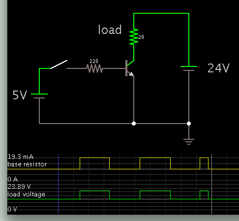
The included image shows the schematics for a scooter's enable line.

Figure 1 shows its normal use; the switch enables the scooter's drive system. Note that there seems to be no appreciable current passing through the switch. I checked it with an in-line ammeter.
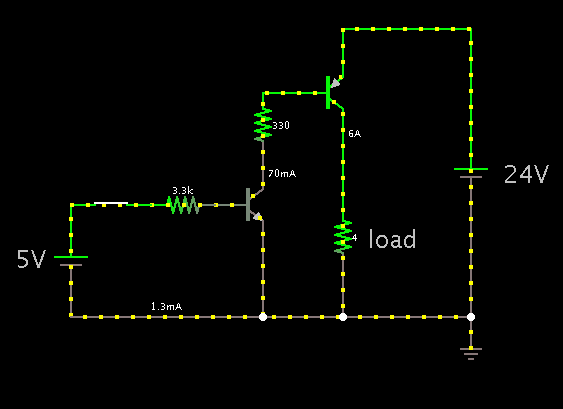
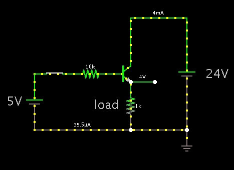
I tried to substitute a transistor for the switch (Figure 2), but it doesn't work. (The 5V simulates an output of a micro-controller.) In fact, I can short out all the resistors and it still won't work; the emitter voltage always reads 3.6V.
What's the solution?
Figure 1 shows its normal use; the switch enables the scooter's drive system. Note that there seems to be no appreciable current passing through the switch. I checked it with an in-line ammeter.
I tried to substitute a transistor for the switch (Figure 2), but it doesn't work. (The 5V simulates an output of a micro-controller.) In fact, I can short out all the resistors and it still won't work; the emitter voltage always reads 3.6V.
What's the solution?