Continue to Site

Welcome to EDAboard.com

Welcome to our site! EDAboard.com is an international Electronics Discussion Forum focused on EDA software, circuits, schematics, books, theory, papers, asic, pld, 8051, DSP, Network, RF, Analog Design, PCB, Service Manuals... and a whole lot more! To participate you need to register. Registration is free. Click here to register now.

Help with Transimpedance amplifier

Status
Not open for further replies.
If i want to simulate a 10Gbps Transimpedance amplifier, what parameter, what value should i get ?

From the sackinger, i know that i need to get transimpedance around
500ohm-2000ohm

Bandwidth around 6Ghz-12GHz


how can i do that ?
what value should i modified to get that ?
btw, my current AC is operating from 0Hz to 10MEG Hz

Added after 7 minutes:

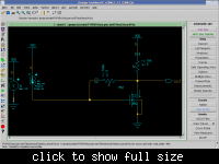
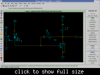
i have changed the value RF to 700k and RL to 10k

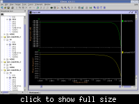
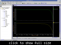
This is my result


If i want DC analysis, what source V should i put and what source Current should i put ?
 

If you want 500 to 2000 ohms transimpedance then that is what your feedback resistor should be (RF). You load would normally be a lot lower than that (RL).

You should be simulating to 10GHz or more.

You need to be careful about what DC current you inject (if any).

Keith.
 

    ricopt

    Points: 2
    Helpful Answer Positive Rating
How do i calculate my RF to transimpedance ?How i know my transimpedance is now within 500ohm to 2000 ohm ?

How do i do DC analysis ?
what source of Voltage and what source of current should i use ?

i am using in my circuit is DC voltage and AC current

If i need to simulate bandwidth what should i change ?what value should i plot ?
 

If you want 500 to 2000 ohms transimpedance then that is what your feedback resistor should be.
Yes, but to achieve 10 GHz bandwidth, the amplifier needs also high voltage gain and low output impedance.
I don't think, that it's feasible with a single transistor.
 

    ricopt

    Points: 2
    Helpful Answer Positive Rating
bro,

I just aim for the lowest that's it.
I having problems with those question .Can you teach me how to do a DC analysis ?What source of voltage should i use ?and what source of current should i use ?

How do you know that 20dB is 10 ohm ?
 

I would suggest you analyse some basic transimpedance amplifiers to gain a better understanding of them before trying to design a 10GHz one.

As I explained earlier, "The transimpedance will be displayed as 20log(Vout/Iin)". Vout/Iin is the transimpedance (=resistance).

Here is a straightforward transimpedance amplifier using an opamp.

The DC analysis shows the slope which is 1Meg ohm, as would be expected.

The AC analysis shows a midband characteristic of 120dB which is the same as 1Meg ohm,as explained above. If you plot simply voltage rather than dB(V) then you get the result shown as 1M.

Keith.
 

    ricopt

    Points: 2
    Helpful Answer Positive Rating
Can anyone explain to me Is my waveform correct for transimpedance ?Why the magnitude is negative

:idea:
 

Why the magnitude is negative
Seems like you managed to cancel the gain completely. I noticed, that you you are continuously modifying
transistor geometry and other parameters, apparently the transistor refused to work now. To understand
what's going on, start with displaying the DC operation point.
 

    ricopt

    Points: 2
    Helpful Answer Positive Rating
i checked ald
the transistor is in saturation mode......but why is like this ?should be working

Added after 5 minutes:

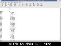
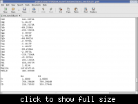
here's my Nmos operation value


Status
Not open for further replies.

Part and Inventory Search

Welcome to EDABoard.com

Sponsor

Back
Top