Continue to Site

Welcome to EDAboard.com

Welcome to our site! EDAboard.com is an international Electronics Discussion Forum focused on EDA software, circuits, schematics, books, theory, papers, asic, pld, 8051, DSP, Network, RF, Analog Design, PCB, Service Manuals... and a whole lot more! To participate you need to register. Registration is free. Click here to register now.

[SOLVED] Help with PIC16F877A!

Status
Not open for further replies.

hkei

Newbie level 6
Newbie level 6
Joined
Jul 31, 2012
Messages
11
Helped
0
Reputation
0
Reaction score
0
Trophy points
1,281
Location
PH
Activity points
1,359
Please help me with my PIC16F877A. It works well on Proteus simulation but it doesn't work with actual hardware as it should be.
All of the voltage terminals are correctly connected to the source including MCLR
The PIC can burn successfully without any problem. So I think there's no problem with the PIC itself. Although,when I write the program on an empty PIC, it only writes 6bytes on the memory (XXXX XXXX XXXX 3FFF 3FFF 3FFF ...).
I don't know what is the problem. I even increase the VDD to 6V from 5V.
The LEDs doesn't output anything

Here are the programs I'm using:
MPLAB IDE v8.50​
HI-TECH ANSI C Compiler​
PICkit 2 v2.61​

Here is the code I found somewhere just to test the LEDs:
Code:
#include<pic.h>
__CONFIG(0x3B31);
void delay_ms(unsigned int x)
{
	unsigned int a,b;
	for(a=x;a>0;a--)
		for(b=110;b>0;b--);
}
void main()
{
	unsigned char i;
	TRISD = 0x00;
	while(1)
	{
		PORTD = 0x01;
		for(i=0;i<7;i++)
		{
			delay_ms(50);
			PORTD = PORTD*2;
		}
		for(i=0;i<7;i--)
		{
			delay_ms(50);
			PORTD = PORTD*2;
		}
	}
}

Here is the configuration bits on MPLAB:
OSC - XT
WDT - OFF
PUT - ON
BODEN - OFF
LVP - DISABLED
CPD - OFF
WRT_ENABLE - 0H TO 7FFH WRITE PROTECTED
CP - OFF​

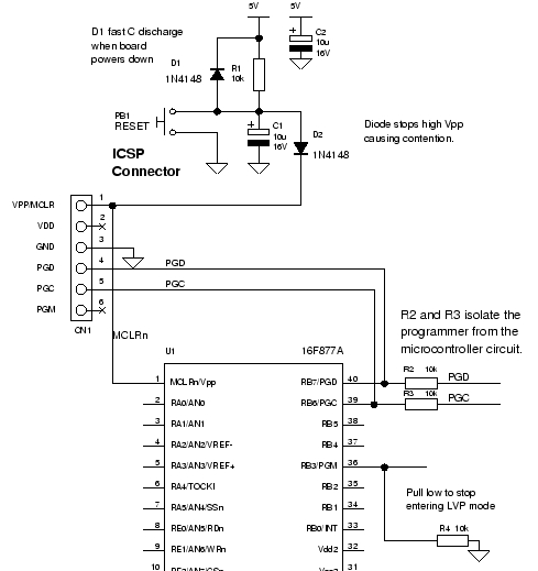
Here is the circuit diagram:
**broken link removed**


Thanks in advance!
 

You usually get this problem if you have the code protection bits set in the configuration byte. When the code protection bits are set you only see the first 6 bytes. I would also suspect the other bits are also set wrong such as the WDT bit. What programmer are you using?
 

Oh I see... but when you change the configuration bits on MPLAB, does the compiler pick that configuration? or the one on the code like __CONFIG(0x3B31)?

I'm using PICkit 2.
 

Oh I see... but when you change the configuration bits on MPLAB, does the compiler pick that configuration? or the one on the code like __CONFIG(0x3B31)?

I'm using PICkit 2.

I don't use the PICKit2 programmer but I would imagine that you should set the configuration in the code like __CONFIG(0x3B31)
 

I changed the WRT_ENABLE bits to write protected off (from 0x3B31 to 0x3F31), pickit2 displayed a verification error so i put back 0x3B31...
All 8 LEDs lighted up. No blinking happened and all the ports can light up the LEDs (I connect LEDs to all the ports). It looks like that the PIC outputs a logic 1 to all the ports.
 

i recently suffered with the same problem while using PIC16F877A, MPLAB IDE v8.83, and Genius G540 programmer; but now the problem is solved. I think we don't know the proper use of MPLAB; its a problemous software for beginners. my problem is solved when i downloaded MikroC compiler form

https://www.mikroe.com/eng/product_downloads/download/

This software is very much easier and user friendly than MPLAB. you can search its tutorials from youtube.

https://www.youtube.com/results?sea...0.0.393.404.1j3-1.2.0...0.0...1ac.3ezHbrcPHJA

Regards
 

@Qaisar Azeemi
I think I'll stick with my resources for now. Anyway, thanks for the recommendations.
 

__CONFIG(0x3B31);
is pretty meaningless?

Better to write it like so you can see what your are setting,

__CONFIG(XT & MCLREN & PWRTEN & BOREN & WDTEN);

You can find examples in the .h file.

You might need to increase your delay time.
50mS is very fast, it might be working but you can't see it.

Also the micro does a read, modify write on the ports.
Try using a variable, like
unsigned char port_output = 1;

PORTD = port_output << 1;
 

Can u check on more thing is what ever hex file that you have is following intel Hex file format or not....

So time the programming file it self may be not upto the standard....

First you try to program the hex file and then read the hex file from the same programmer and check that you are getting match of what you are written in the PIC ( read file from PIC) and what is existing in file that is used to program....As per my knowledge PICkit2.0 support read operation of hex file from PIC if code protection is not turned on...

the second point is as we see your code .....it is very small so may be hex file it self will be small to program....I think you should increase delay to see the output also I think you need to check your code also bcz PORT = PORT*2 dose not mean any thing ....first try out LED blinking from any of the port pin like

Code:
PORTD=0x03; // Port pin 0 and 1 are high

dealy_ms(1000)

PORTD= 0x00;// Port pin 0 and 1 are Low


and check that you are getting toggle of port pin first to gain the confidence....

Good Luck
 

Thanks for the lectures!
I've tried to modify the code (I just replace 50 to 1000 on the delay_ms). But another problem occurred.
There's a problem in programming. On PICkit2, it says "Program Memory is not blank starting at address 0x000000". It displays when I Blank Check the PIC. Now, I can't erase the what's written on the chip.
What's the best thing to do? I can't replace the chip now. The electronics stores are too far away.
 

Have you tried simply erasing the device, not programming it? And then performing a blank check on the device.

You may have inadvertently enabled Code Protection.

BigDog
 

Have you tried simply erasing the device, not programming it? And then performing a blank check on the device.

You may have inadvertently enabled Code Protection.

BigDog

Yes Sir, I've tried to erase first. I get the error when I blank check it and it really is not blank because there's still values on it.
How can I disable the Code Protection?
 

Code Protection is enabled through the Configuration Register settings.

I'm not sure of the settings the following compiler directive produces, however it overrides the settings in the MPLAB IDE.

In any event, erasing the entire device should remove any Code Protection.

Can you post a schematic of your circuit? There maybe issues with the programming/debugging interface.

I also noticed you are operating the device above its maximum operating voltage. Doing so can permanently damage the device, so do NOT.


BigDog
 

The code protection is turned off in MPLAB.

The schematic diagram of my circuit is on top, my first post.
 

The code protection is turned off in MPLAB.


Then remove any form of the compiler directive:

Code:
__CONFIG( );


The schematic diagram of my circuit is on top, my first post.

Sorry, I hadn't noticed it.

Reduce the operating voltage to 5V.

Pull the RB3/PGM pin low, this disables LVP and is sometimes an issue.

Do you have anything other than the PICkit attached to RB6/PGC or RB7/PGD?

Is the MCLR/Vpp connection from the PICkit to the device direct?


BigDog

- - - Updated - - -

A typical minimum programming/debugging circuit:

40_1343814867.jpg


You should also ensure there are bypass capacitors installed across Vdd and Vss as close to the PIC as possible, typical values are 0.1uF.
 

Pull the RB3/PGM pin low, this disables LVP and is sometimes an issue.

Do you have anything other than the PICkit attached to RB6/PGC or RB7/PGD?

Is the MCLR/Vpp connection from the PICkit to the device direct?

Yes all the pins from the PICkit (aside from AUX) when programming are directly connected to the device except for the Vcc and Vdd which have bypass capacitors. That's just while programming, but during the test, I follow my schematic.
 

Is your clock properly defined?

What do you mean by properly defined?

I use 4MHz and two 18pF caps. But according to datasheet, XT osc type in 4MHz should be 15pF. It's okay to use 18pF right?

The OSC bit is in XT
 

It works wonderful now!
I just replace a new PIC and put an external voltage of 6V and regulated as 5V (using 7805) power on the PIC during the programming process. It seems that my PICkit is very faulty. I also didn't notice last time that the pins of the oscillator was connected on the 13 and 15 pins of the PIC.

One thing that I didn't solve is the Program Memory error on my previous PIC.
 

an external voltage of 6V and regulated as 5V (using 7805)

What voltage is the PIC getting? a 7805 has a dropout of at least 2V!
 

Status
Not open for further replies.

Similar threads

Part and Inventory Search

Welcome to EDABoard.com

Sponsor

Back
Top