KJ6EAD
Advanced Member level 3

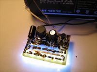
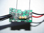
The converter as purchased was running ≈20kHz. It's now ≈75kHz.These converters should already be running about 70kHz.
The only chance of measuring the frequency digitally is at pin 3…
Lmin = ( (Vin(min) - Vsat(sw) -Vout) / Ipk(sw) ) * ton(max)
What current and voltage are you trying to achieve now for the converter?
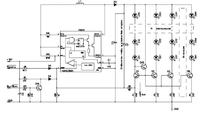
The MC34063A as configured produces less than 300mV on pin 3. My Fluke meter can measure it but Sabrina's meter needs at least 500mV to measure Hz.
The design goal is 3.4V @500mA. We've got the voltage and are trying to increase the current.
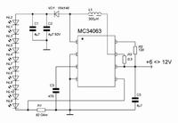
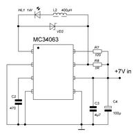
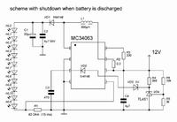
I've been using the On Semiconductor MC33063/MC34063 design worksheet but some component specifications are unknown. Semiconductor and Integrated Circuit Devices
Using the formula for Lmin, the design value could be as low as 32µH and as much as 63µH depending on other (partially known) variables. This is a minimum value and it's likely that the Chinese designer went to the low side of this range or less and assumed a 500mA ripple current (100% inductor saturation) to save cost. By changing the inductor to 220µH, we should be able to run as low as 29% saturation and still get our required current out. I'm intentionally building in some margin so that if we have to change anything later, it will be something cheap, like a chip capacitor or resistor.
Last edited:


