Continue to Site

Welcome to EDAboard.com

Welcome to our site! EDAboard.com is an international Electronics Discussion Forum focused on EDA software, circuits, schematics, books, theory, papers, asic, pld, 8051, DSP, Network, RF, Analog Design, PCB, Service Manuals... and a whole lot more! To participate you need to register. Registration is free. Click here to register now.

Help on Inverter problem

Status
Not open for further replies.
This can happen if the frequrncy of the oscillator is lower than 50Hz. How do you check, if the frequency is right?
Another possibility is that the transformer is not for 48V but for less, for example 36V. This is easy be verified and you already be knowing. Did you check 48V on individual winding with multimeter while connecting 220V side with mains. The outer wires will show 96V AC.


I check the frequency of oscillation with my multimeter because it measures frequency. I do place one terminal of the meter at one of the output terminal of the oscillator while the other terminal of the multimeter is connected to the other output of the oscillator. Am I not right? Should I measure between each of the output terminals and the ground?

Concerning the transformer, when i connected 220V AC at the input it gave me 48V-0V-48V.
 

Meter will give false fequency reading because there is a dead-band in the waveform. Put one lead to ground and see frequency and duty-cycle on either of the outputs.
Pin#3 of SG3524 is oscillator output pin. Checking frequency between it and ground will be more accurate.
But here the frequecy will be double. Set it for 100Hz if checking on pin3.
 

I have checked the frequency on pin 3 and is given me 100.9 Hz.
 

In addition to frequency counter, there is an option in multimter to check the duty cycle of the wave. It should be less than 45% at output of IC and ground. Soft-start also help in reducing initial surge. When you checked with bulb, it was dim that means it worked quiet well in this condition. Repeat this test and also with fuse three or four times to see it always happens like this. First connect 48V and after that connect power to oscillator. Post a few pics of your whole setup.
 

Please don't mind how untidy the picture is, I have been adding and removing since the problem started.
This is a picture of the oscillator circuit together with the intelligence unit (battery monitor and the rest):
https://obrazki.elektroda.pl/3279563000_1381228039.jpg

This is the whole picture
https://obrazki.elektroda.pl/1837980500_1381228357.jpg

- - - Updated - - -

Concerning measuring the duty cycle, I am using MY68 Mastech multimeter. I don't think it can measure duty cycle. Please if it can measure duty cycle let me know how to set it and how to measure the duty cycle
 

I have 2kVA inverter that I just built. During testing I just connected a 100watt bulb and it was working for about 10minutes but when i connected a 150watt fan to it , the bank of MOSFET got burnt.
Since then I have replaced the MOSFETs and connected no load to the Inverter output but at switch ON the MOSFETs still got burnt.
At no load should the inverter draw current from the battery to the extent that it can burn the MOSFETs?
Please can someone help me and tell me the possible cause of the problem.
SG3524 dose not have dead time delay which is very important in a inverter design . Try using sg3525 very good and stable. It can directly drive mosfets. If you are using above 12v then add a regulated power to sg3525
 

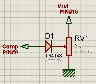
your meter hs not facilit to check duty-cycle. It does not matter. Make this modification to your oscillator circuit by adding a diode and variable resistor as shown. This will make a control over dead-time.

3157598700_1381265662.jpg


set variable wiper towards ground. there will be no current drawn and no output. slowly rotate towards +ve side. Voltage will start coming out. Set the current less than a ampere. Best setting is where the humming from transformer lowers but output voltage does not fall more tha 20V.You can use other value for pot if you don't have this 5k.
 

Please remember that I am using a feedback network connected to the pin1 for voltage regulation. I hope the connection you asked me to make will not have any effect on the voltage regulation.
Please is humming a problem to transformers?
 

It ill only increase deadtime. ulation will still work. Humming is high when there is less deadtime due to hard switching but it is not a problem. Some loosing of steel sheets and winding cause this which is natural becaus3e there is a limit who tight you stack.
 

I forgot to tell you that I already have some components connected to pin 9. As usual, I connected a 1nF capacitor from pin 9 and the other terminal of the capacitor is pulles to the ground by a 27k ohm resistor. Should I still continue with the connection?
 

Yes, that is filter. That will not pose any problem.
 

I later resolved using sg3525 and the inverter is working well now.


ALERTLINKS, thank you very much.
 
Last edited:

Status
Not open for further replies.

Similar threads

Part and Inventory Search

Welcome to EDABoard.com

Sponsor

Back
Top