- Joined
- Jan 22, 2008
- Messages
- 53,094
- Helped
- 14,792
- Reputation
- 29,871
- Reaction score
- 14,289
- Trophy points
- 1,393
- Location
- Bochum, Germany
- Activity points
- 300,990
Re: 1/2 kW SMPS 2-50V 0-10A
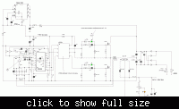
The current sense is a standard feature of current mode PWM controllers. It's not intended to sense the output current. It's an auxilary control loop to improve the dynamic behaviour of the main control loop and a means to protect the switcher against overcurrents. You'll find detailed explanations of current mode in text books and PWM controller applications notes.
The auxilary winding providing the voltage feedback is primarly used as low voltage power supply. The 220k resistor is only sourcing a small start-up current, not able to supply the controller in operation.
A secondary voltage feedback will achieve better regulation but auxilary winding feedback is often sufficient for basic requirements.


