Continue to Site

Welcome to EDAboard.com

Welcome to our site! EDAboard.com is an international Electronics Discussion Forum focused on EDA software, circuits, schematics, books, theory, papers, asic, pld, 8051, DSP, Network, RF, Analog Design, PCB, Service Manuals... and a whole lot more! To participate you need to register. Registration is free. Click here to register now.

Help me debug what is wrong with my Commodore 1084S-P CRT Monitor

Status
Not open for further replies.
@Relayer I measured the voltages around TS467. Collector is 22.1 V DC, base is 0.025 V DC, and emitter 0.02 V DC.

I also tested transistor TS132. The base-emitter resistance is 0.646 * 2k ohms and base-collector resistance is 0.570 * 2k ohms. Punch through tests were ok.
--- Updated ---

@Relayer More progress. I lifted the cathode leg of D141 and connected two light bulbs (40W and 60W) in series to the anode leg. I used the negative side of C144 as grounding point as instructed. The whistling was gone. Does this rule out PSU as being the faulty component?
 
Last edited:

Sorry for my lack of response. I've been a tad busy of late.

I measured the voltages around TS467. Collector is 22.1 V DC, base is 0.025 V DC, and emitter 0.02 V DC.

OK. Looks like the main HT rail is down. 21.1 volts is hardly enough at the collector of this transistor.
This we need to investigate.

More progress. I lifted the cathode leg of D141 and connected two light bulbs (40W and 60W) in series to the anode leg. I used the negative side of C144 as grounding point as instructed. The whistling was gone. Does this rule out PSU as being the faulty component?

Damn. I should have gotten you to measure the main HT rail while you had it in the above condition.
The HT rail should be at 125 volts. It should have also been on the collector of TS467.
Yes, as you've said, we need to rule out the PSU as being faulty, but there's still a possibility that other voltage
rails are not being generated or are lower than what is required.

Next step is to isolate the PSU once again from the rest of the motherboard.
You need to disconnect D141 again and place those globes across it.
You need to measure the voltage at the cathode of D141. Hopefully it will be at 125 volts.
Next, you need to measure the other voltage rails coming out of the PSU.
Measure the 16 volt rail at the junction of D143 and C146.
Next, measure the 12 volt rail between Pin 3 (Output) of IC403 (which will be a 12 volt regulator) and C492.
Measure TS235, all pins. They should read 8.7V at the base, 8.2V at the collector and 5 volts on the emitter.
Lastly, measure between D142 and C145. This should be at 26 volts.
Remember to use C144 as the grounding point once again.

Please let us know how you get on.
Regards,
Relayer

EDIT
I keep forgetting to ask you: Are you getting anything on the screen at all while
the monitor is whistling? If not, are you feeding the monitor with a signal?
 
Last edited:
@Relayer Thank you! Could you explain why you want the light bulbs connected to the anode leg of D141 and not to the cathode leg?

I do not get anything on the screen at all when the monitor is whistling nor am I feeding it with signal. The monitor lighted up without signal before I broke it.
 

Could you explain why you want the light bulbs connected to the anode leg of D141 and not to the cathode leg?

It's not really critical whether the lightbulbs are on the cathode or anode side, as the globes are there as
a dummy load for that part of the PSU's main output. But you need to measure on the cathode side to get
the 125 volt rail. You can use the ground point of C144 for your ground reference, but it's not critical. You can use
any other ground point on the cold side. eg. The ground on TS152, C152, R152 etc.
Regards,
Relayer

EDIT
Can I get you to physically look at C471. It's a 470uF (50 or 100 volt rating) bi-polar electrolytic capacitor located close to the yoke connector.
Have a look to see of it's deformed in any way, as well as see if the the label has shrunk in at all. Look at the top of the
cap, and you might see that the label has pulled away compared to other electrolytic capacitors.
Thanx.
 
Last edited:
I got new BYD33D in the mail and measured them. They show no leakage when punch through tested. Should I go ahead and replace D143?

Also, my ESR meter arrived so I can now check capacitors.

You first need to check out one electrolytic capacitor in the primary of the power supply.
i.e. C122 (1uF 100V)

Did you perhaps mean C112? Well here are the capacitances for both:

C112 (400V 100uF):
Cap = 105.8uF
ESR = 0.22ohm
Measured in circuit

C122 (50V 1uF):
Cap = 1.08uF
ESR = 1.22ohm
Measured outside circuit

Can I get you to physically look at C471. It's a 470uF (50 or 100 volt rating) bi-polar electrolytic capacitor located close to the yoke connector.
Have a look to see of it's deformed in any way, as well as see if the the label has shrunk in at all. Look at the top of the
cap, and you might see that the label has pulled away compared to other electrolytic capacitors.

C471 ( .47K DC250V PPN/TSC):
Cap = 7.22uF
ESR = 0.00ohm
Measured in circuit

The ESR value looks good but the capacitance is way off.

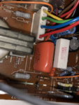
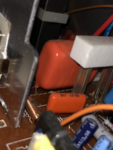
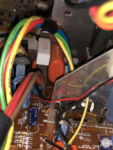
It looks ok to me, but here is a couple of pictures so you can see for yourself.
IMG_9194.pngIMG_9195.pngIMG_9196.png

You need to disconnect D141 again and place those globes across it.
You need to measure the voltage at the cathode of D141. Hopefully it will be at 125 volts.

Today I got strange results while measuring voltage at the cathode leg of D141. The results are best explained via video.


As can be seen from the video, the PSU stays quiet at first but with repeated on/offs it starts to whine. The whining sound is different this time. I measured the voltage at the cathode leg to be 3.1V when the PSU does not whine and 42.7V when the PSU whines.

Measure the 16 volt rail at the junction of D143 and C146.

0.27V at the D143 cathode leg

Lastly, measure between D142 and C145. This should be at 26 volts.

11.9V at the D142 cathode leg.

I reconnected the PSU to monitor to measure the the following
Next, measure the 12 volt rail between Pin 3 (Output) of IC403 (which will be a 12 volt regulator) and C492.
Measure TS235, all pins. They should read 8.7V at the base, 8.2V at the collector and 5 volts on the emitter.

But apparently something in the PSU has changed (or atleast the whining has changed). The new sound can be heard from the following video:


It seems that the PSU is broken after all.
 

Hello horttanainen,
Please excuse the lateness of my reply. I've been very busy etching PCB's.

Should I go ahead and replace D143?

Yes. Replace it, as the old one does have leakage.
I doubt it will fix your problem though.

Did you perhaps mean C112? Well here are the capacitances for both:

Going by your ESR readings, both C112 and C122 should be fine.

C471 ( .47K DC250V PPN/TSC):

Very strange you got 7.22uF as the reading, since it's supposed to be 0.47uF???
I got that cap wrong. I assumed it was a bi-polar electrolytic. My bad.
I'd say C471 is fine.

Your first vid shows the PSU virtually giving no output at all. Strange once again.
It does seem the power supply is the root of the problem.

Your second vid just shows how sick that puppy really is.

OK, since we know it's the PSU itself, you need to do the following:

Before you start though: Be extremely cautious around the primary of the power supply.
You have no transformer to isolate you from the mains.
Make sure to remove any rings or a watch you may be wearing.
It would be best to measure with the main PCB board with the components below
and you facing the copper side of things.
If you ever need to physically touch (with your finger) any solder joints
(with the power off of course) make sure you discharge the main filter cap (C112).
It would be preferable to use a 120 ohm 5 watt resistor as a bleeder, as this will
discharge it with no sparks. But if you have nothing handy, you can use an insulated
screwdriver. But be prepared for a spark or two.
Use the negative end of the main filter cap (C112) as your ground reference point for the rest
of your measurements.

(1) Measure the voltage across the main filter capacitor C112. It should be around the 300 volts plus
DC. Perhaps around 330 volts more or less.
(2) If it does read in the 300 volts +, then measure TS121 and TS132. Check to see if they match up to
the indicated voltages on the schematic.

Please let us know how you get on.
Regards,
Relayer
 
Hello @Relayer ,
and thank you very much for your time and continuing efforts in helping me.

I replaced D143. As suspected this did not fix the problem, nor did it make any visible change.

I measured C122, TS121, and TS132 with the main PCB board with the components below and facing the copper side of things.

C122:
320V DC

TS121:
Collector 0.035V DC (should be 3.7V)
Base -0.08V DC (should be 7.4V)
Emitter 0V DC (should be 5.5V)

TS132:
Collector 321V DC (should be 77V)
Base 0.37V DC (should be 75V)
Emitter 0.5V DC (should be 75V)

I used the negative side of C122 as grounding point for the above transistor measurements. This is a "hot ground". I do not know what "hot ground" means so I am unsure if this was a good grounding spot. My PCB lacks the diode D111 (present in some of the schematics) and thus could not use its anode as grounding point.
 

Hello horttanainen,

C122:
320V DC

At least there is the correct voltage at the mains filter capacitor.

TS132:
Collector 321V DC (should be 77V)

The above shows the transistor isn't switching.

This is a "hot ground". I do not know what "hot ground" means so I am unsure if this was a good grounding spot.

Click on the modified schematic below:


Notice the different ground symbols between the HOT and COLD sides.
In the old days, before switch-mode power supplies were the norm, most electronic equipment was supplied
with a power transformer, which isolated a technician from direct contact with the mains of 120 volts or 240 volts
AC. Due to no physical contact within the power transformer, it was considered isolated. The transference of power
is due to the inductance between the primary and the secondary side of the transformer.
It was considered as relatively safe to work on the secondary side of the transformer. A person with a poor heart
condition may receive a fatal shock from the secondary, but in most cases it can be considered safe.
Switch-mode designed PSU's on the other hand can pose a significant risk to a technician of he/she isn't careful.
The is NO isolation transformer, except for the chopper tranny (T101 in this case). Therefore you could accidentally
touch a live component and cop the full 8 or 16 amps (Household fuses) of current that can potentially kill.
On the rare occasion whist I was doing electronic domestic appliance repairs, I got belted by the hot side of a PSU
but I was fortunate. All's I copped was my pride being hurt.
Switch-mode PSU's are way more efficient than the transformer types. Way less wasted heat.
So it seems switch-modes are with us to stay. Though you may see some audio gear still using transformers.
Sensible technicians will use an isolation transformer to make it much safer to work on live circuits.
This is an external tranny that is plugged in between the mains and the equipment being worked on.
Isolated transformers are not overly expensive, but anyone can make one using two identical trannys
by connecting the secondaries together. Earth would attach to both transformer bodies.
The current capability will depend on the transformers specs.

I hope the above has given you an idea of HOT and COLD sides within switch-mode power supplies.

Now, let's get back to your monitor.

Since your PSU isn't overly complicated, I need to get you to start some ohms measurements.
You need to check all the resistors on the HOT side. You can try measuring with them in-circuit,
but if you get erroneous readings, then you'll have to remove one end of the resistor to obtain the
correct value.
If you find nothing wrong, then you need to visually inspect any capacitors that may be malformed
or have a physical defect.

Please let us know how you get on.
Regards,
Relayer

EDIT
Is it possible for you to read the part number of TS152 please. It looks like an SCR.
 
Last edited:
@Relayer Good morning! I was just about to get to sleep but the thunder kept me awake.

Thank you for clarifying the difference between HOT and COLD sides and their respective grounds. I think I have to acquire and isolation transformer for safer future work.

Is it possible for you to read the part number of TS152 please. It looks like an SCR.

The component reads:
PH
BT151
500R
m8827

Since your PSU isn't overly complicated, I need to get you to start some ohms measurements.
You need to check all the resistors on the HOT side. You can try measuring with them in-circuit,
but if you get erroneous readings, then you'll have to remove one end of the resistor to obtain the
correct value.
If you find nothing wrong, then you need to visually inspect any capacitors that may be malformed
or have a physical defect.

I will check the resistors and capacitors in the morning
 

Hello @Relayer

Since your PSU isn't overly complicated, I need to get you to start some ohms measurements.
You need to check all the resistors on the HOT side. You can try measuring with them in-circuit,
but if you get erroneous readings, then you'll have to remove one end of the resistor to obtain the
correct value.

I measured all the resistors on the HOT side. Only one resistor required lifting its leg to get the correct value. Funny coincidence that this resistor, R136, was the single most hardest to get to resistor on the board. All resistors matched their indicated values. However, for some reason resistor R121 (listed as 390K carbon film resistor, which was actually a 1.5M resistor) gave different readings when changing measurement direction. 1.39M to one direction and 1.1M to other direction. Despite this strange feature, I gather that this resistor is fine.

If you find nothing wrong, then you need to visually inspect any capacitors that may be malformed
or have a physical defect.

Upon visual inspection all the capacitors on the PSU board appear to be fine. However, I did in circuit ESR measurements and got some large ESR values for at least a couple of the capacitors and a lot of in circuit/leaky readings. I will lift the legs of most of the capacitors tomorrow to get better readings.
 

R121 (listed as 390K carbon film resistor, which was actually a 1.5M resistor)

Do you mean the color bands are 1.5 M?

large ESR values for at least a couple of the capacitors

As ESR became better known there were repair technicians who reported that ESR testing turned out to be the definitive measurement for tracking down certain equipment problems.
Equipment that was hard to diagnose worked after they installed low-ESR capacitors.
 
Do you mean the color bands are 1.5 M?
Yes.

As ESR became better known there were repair technicians who reported that ESR testing turned out to be the definitive measurement for tracking down certain equipment problems.
Equipment that was hard to diagnose worked after they installed low-ESR capacitors.
I am glad that I purchased the ESR meter right from the start of this debugging journey.
--- Updated ---

Hello @Relayer,

it turns out that my Peak Electronic ESR70 meter can only handle capacitators above 1uF. All capacitors above 1uF gave excellent capacitance and ESR readings.
 
Last edited:

it turns out that my Peak Electronic ESR70 meter can only handle capacitators above 1uF. All capacitors above 1uF gave excellent capacitance and ESR readings.

Most capacitors below 1uF are non-electrolytic or non-tantalum. They do go as low as 0.47uF with Tant's and electro's.
All other types of capacitors i.e. ceramic, polyester, monolythic etc. should have basically zero ESR.
ESR testers are almost exclusively used on electrolytic types of caps.

At this point I'm at a loss as to what my be the problem with your monitor.
It's possible that it's a voltage feedback problem. Something to do with the drive circuitry for IC101 and TS117.
It wouldn't hurt to test the following:
TS117, R112, R113, R115, R116 and R117.
Also wouldn't hurt to check the ESR on: C116, C144, C145 and C146.

Please let us know how you get on.
Regards,
Relayer
 
@Relayer,
sorry for keeping you awaiting. Here are the latest measurments:

TS117, R112, R113, R115, R116 and R117.

I had measured TS117 earlier. Base to emitter resistance was 844 ohms and base to collector resistance 839 ohms. I recall that the punch through test was ok too.

Resistors R112 to R117 are ok.

Resistor R114 is a potentiometer which should be set at 1K according to the schematic but is actually set at 250 ohms.

Also wouldn't hurt to check the ESR on: C116, C144, C145 and C146.

ESR readings for these capacitors are excellent and the capacitance readings match their indicated values.

Do you have any more ideas on how to debug this PSU?
--- Updated ---

Hello @Relayer ,
and thank you very much for your time and continuing efforts in helping me.

I replaced D143. As suspected this did not fix the problem, nor did it make any visible change.

I measured C122, TS121, and TS132 with the main PCB board with the components below and facing the copper side of things.

C122:
320V DC

TS121:
Collector 0.035V DC (should be 3.7V)
Base -0.08V DC (should be 7.4V)
Emitter 0V DC (should be 5.5V)

TS132:
Collector 321V DC (should be 77V)
Base 0.37V DC (should be 75V)
Emitter 0.5V DC (should be 75V)

I used the negative side of C122 as grounding point for the above transistor measurements. This is a "hot ground". I do not know what "hot ground" means so I am unsure if this was a good grounding spot. My PCB lacks the diode D111 (present in some of the schematics) and thus could not use its anode as grounding point.

I was wondering if it was okay to do these measurements with the PSU connected to the monitor? Could a short on the monitor side cause the voltages to be missing?
 
Last edited:

I am about ready to chug this monitor into the bin but it seems such a waste as the problem seems to be in the PSU which atleast appears to be simple.
 

Hello horttanainen,
Please excuse the lateness of my reply.
I have to admit that trying to diagnose from a distance can be very difficult.
I'm now at a loss at what to do next.
If I had the monitor at this point, I would start replacing components. Since
component testing is never 100%.
You can try replacing TS121 and TS132.
Also consider replacing C122, even though it's ESR was within tolerance.
It's capacitance may be way down.

I was wondering if it was okay to do these measurements with the PSU connected to the monitor? Could a short on the monitor side cause the voltages to be missing?

Yes. You can do voltage measurements with the PSU connected to the monitor.

Yes. A short on the monitor side would definitely cause voltages to be missing on the
output of the PSU.

What you can do at this point is do an ohms measurement on each PSU output.
Here are the points you should measure, but make sure everything is connected,
e.g. Resistors and/or diodes lifted for measurements and of course with no
power connected:

D141 cathode to ground (negative side of C144 as an example)
D143 cathode to ground (any secondary ground point)
D142 cathode to ground (any secondary ground point)
C492 positive side to ground (any secondary ground point)
TS235 emitter to ground (any secondary ground point)

If any of these measure short or very low ohms, then there will be a problem.

Please let us know how you get on.
Regards,
Relayer

P.S. I'll try to respond a bit quicker in the future. Sorry once again.
 
Not sure if it's worth mentioning, but I bought a Commodore 1942 monitor recently with this exact same issue and came across this thread when searching for a fix. Here's what I did to fix it in the end:

- reflowed every solder joint on the board (and neckboard)
- replaced the IC responsible for vertical deflection (in my case a TDA1675A)

It started working after that but was far too bright, I had to turn down the main flyback control ("SCREEN"), adjust the sub-brightness POT to zero, and slightly turn down the separate B+ voltage POT to get it to a regular brightness. I'm thinking there might be some iffy capacitors somewhere.

Anyway, best of luck with the repair!
 
Hello @Relayer,
and thanks for the reply.

You can try replacing TS121 and TS132.
Also consider replacing C122, even though it's ESR was within tolerance.
I will order replacement parts for these components. I have the replacement for C122 and I might have the replacement for TS121. TS121 is a C33740 PH 84 and I have a F 508 BC33740 around. I think this should be suitable.

D141 cathode to ground (negative side of C144 as an example)
D143 cathode to ground (any secondary ground point)
D142 cathode to ground (any secondary ground point)
C492 positive side to ground (any secondary ground point)
TS235 emitter to ground (any secondary ground point)
D141 cathode to C144 negative measured 240 ohms.
D143 cathode to every tested secondary ground point measured 1 ohms. (this is the diode I replaced)
D142 cathode to C144 negative measured 5K ohms.
C492 positve leg to C144 negative measured 240 ohms.
TS235 emitter to C144 negative measured 200 ohms.

So there is a short with something connected to the D143. Where do you think I should start looking? I will check the immediate neightbouring componets tomorrow.

Also, could you point me this component @DeChief mentioned on the schematic?
replaced the IC responsible for vertical deflection (in my case a TDA1675A)
Is it the TDA2595 (IC402)?
 
Last edited:

Hello horttanainen,

and thanks for the reply.

You're welcome.

I have a F 508

Never heard or seen this type???


This must be a BC337 in a TO-92 package. This seems right.

What is the part number on TS132?

So there is a short with something connected to the D143

Most definitely. I really should have gotten you to do this test in the first place.
It would have saved time. My bad, sorry about that.

By the way, it seems there's no need to replace TS121 and TS132, so don't sweat
it. Also, no need to replace C122.

Since D143 supplies 2 voltage rails (16 volts and 12 volts), we need to eliminate one
from the other.
You need to desolder and remove IC403. This is the 12 volt regulator IC. Then remeasure
on ohms, D142 and a good secondary ground point to see if it still measures 1 ohm.
If it doesn't, the the culprit will be IC403.
If you'd rather not remove the IC, then just desolder the input pin and make sure it's
totally isolated from the circuit.
If it still does measure 1 ohm, then the process of finding the short will be a bit more
tedious.
We now have to look at all parts on the motherboard that gets fed 16 volts and eliminate
each section in turn.
After a close look at all the schematics, it seems the 16 volt rail is only used in the audio
section of the monitor. But the 12 volt rail is used in a multitude of places. Feeding all the
other IC's their voltage rails.

At this point though, I'm favoring DeChief's prognosis that it could easily be the IC he
mentions (TDA1675A), though I take it that's not the one installed in your monitor?
You mention TDA2595.
Your's does similar functions to DeChief's one.
An yes, it's IC402.

If the test on the 12 volt regulator IC shows that there still is a short, then you need to
isolate pin 15 of IC402 to see if the short disappears.
If the short remains, then we need to look elsewhere. But if the short does disappear,
then IC402 is unserviceable.

Please let us know how you get on.
Good Luck!!!
Regards,
Relayer


Status
Not open for further replies.

Part and Inventory Search

Welcome to EDABoard.com

Sponsor

Back
Top