Continue to Site

Welcome to EDAboard.com

Welcome to our site! EDAboard.com is an international Electronics Discussion Forum focused on EDA software, circuits, schematics, books, theory, papers, asic, pld, 8051, DSP, Network, RF, Analog Design, PCB, Service Manuals... and a whole lot more! To participate you need to register. Registration is free. Click here to register now.

Heat Sink Design

engr_joni_ee

Advanced Member level 3
Joined
Nov 3, 2018
Messages
807
Helped
2
Reputation
4
Reaction score
7
Trophy points
18
Activity points
6,730
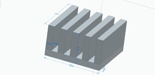
I have designed a heat sink.

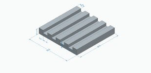
The dimensions are shown in attachment. I am bit concerned with the 1.5 mm.
Is that possible to manufacture ?

HeatSink01.jpg


HeatSink011.jpg


HeatSink013.jpg
 

Attachments

  • heat-sink-design-for-thermal-analysis.pdf
    1,003.1 KB · Views: 23
Really it's too slim - 2.5mm min - a thicker base allows heat to spread t the fins better too !

are you going to get this extruded ? a slant on the fins will help = narrower at the top !

as will rounded fillets where the fins meet the base
 
"Skiving" can do the fins but why is this a matter for design rather than selection? It doesn't look any kind of exotic to me. And not particularly "designed" from the look of it either. Assembled in CAD space maybe.
 
I did some changes. Now it is 2.5 mm. I made two versions. Kindly let me know if we can manufacturer in Aluminum.
 

Attachments

  • HeatSink01.jpg
    HeatSink01.jpg
    92.9 KB · Views: 14
  • HeatSink02.jpg
    HeatSink02.jpg
    96.9 KB · Views: 14
Hi - just the base should be 2.5mm - the fins are OK as previous - obviously thinner at the tips make manufacture easier - as does a filleted base.
 
Hi,

still the discussion makes no sense as long as the manufacturing method is not clear.

There are so many methods: EasyPeasy mentioned the preferred method: extruding ... but no reaction from the OP at all.

There are so many methods ... for some you have more restrictions and design limitations .. for others less.

Extruding, sawing, milling, 3D printing, wire EDM, stamp EDM, pressing, casting...

My way would be: decide the manufacturing method then contact an according company about design resitrictions.

Klaus
 
I did some changes. Now it is 2.5 mm. I made two versions.
So, are you doing a trial and error method with no 'science' behind? Are you aware that the intensity of the heat flux impacts the determination of the thickness of the heatsink base, as well as how much of the surface of this heatsink is in contact with the (metal?) surface of the heat source? That depending on whether there is not forced ventilation, this may impact on the need to increase or not this thickness, as well as to move the fins apart each other? As Klaus mentioned, important aspects of this design are not being addressed.
 
Just to echo what’s been said, why wouldn’t you buy an off-the-shelf component? there are LOTS of extrusions that you can buy and cut to length. I can’t believe you can’t buy what you need.
 
Hello again,

I have read the document in #3 about heat sink.

I have found the datasheet of a heat sink. The datasheet presents the graphs for different sizes of heat sink.


I have attached a graph of a heat sink in which the height, length and width are 19 mm.

What do different curves on the graph are representing ? Are they representing different patterns/footprints ? Are they representing different height ?

The height 19 mm is the same as length and width. It should be number of patterns/footprint but the number of patterns/footprints are 19, 21, 23, 27, 29, 31, right ? I am not sure how it shows curves for different heights.

Untitled 774.png
Untitled 775.png
 
It says "Thermal Performance Based on Height". This means that each curve is representing height.

From the graph it look like higher the height of the heat sink, lower is the thermal resistance.

I am wondering about what are the "footprints" available in 19, 21, 23, 27, 29, and 33. Is this number of fins ?
 
I am not sure how it shows curves for different heights.

In simple words, the highest values in the vertical axis of the curve, the worst performance.
Thermal resistance (oC/W) means the opposition (ΔoC) to let the heat (ΔW) flow through the heatsink.
 
Thanks for reply.

I am still wondering about "footprints".

Is it possible to get the 3D step model file for these heat sinks from Wakefield Thermal website.
 
Sorry for coming again. But I don't find the 3D step model file for the given heat sink from Wakefield Thermal website. Kindly let me know if there is any other way to get the step file. Thanks in advance.
 

LaTeX Commands Quick-Menu:

Similar threads

Part and Inventory Search

Welcome to EDABoard.com

Sponsor

Back
Top