Continue to Site

Welcome to EDAboard.com

Welcome to our site! EDAboard.com is an international Electronics Discussion Forum focused on EDA software, circuits, schematics, books, theory, papers, asic, pld, 8051, DSP, Network, RF, Analog Design, PCB, Service Manuals... and a whole lot more! To participate you need to register. Registration is free. Click here to register now.

Having issue with SMPS circuit

PriyanshuGupta

Newbie level 4
Newbie level 4
Joined
Dec 10, 2024
Messages
6
Helped
0
Reputation
0
Reaction score
0
Trophy points
1
Visit site
Activity points
30
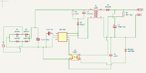
I am currently working on a project to build a 240V AC to 5V 2A DC SMPS circuit.
I have designed the circuit based on the standard flyback converter topology, but I’m facing some issues that I can't resolve.

I hope someone here can guide me through troubleshooting this.

T1 -ee20 , 203T Primary 0.1mm, 4T Secondary 0.5mm
D5 - 1N4734A
R1 - 100k ohm
C5 - 103/1KV
Screenshot 2024-12-10 173011.png
 
Last edited:
the bridge rectifier itself got short circuit
these diodes usually are rather robust. If they are short circuit .. then I expect a different problem else where.

Can you show a photo of your circuit (100kBytes should be sufficient)

Klaus
 
Stenzer is right.

A switch mode power supply needs
* low impedance switching paths
* high voltage isolation
None of them a perfboard can provide.

Thus there is a good chance that your "prototyping technique" creates the problem you see.

This is one reason why I do almost no "true" prototypes at all. I design the circuit according datasheet and then create PCB that almost looks like the end product.

The PCB layout for a switch mode power supply is responsible for
* proper operation
* clean switching
* stable regulation loop
* EMI and EMC
None of the above can reliably tested on a perfboard.
Then I ask myself: what information do you gain by a perfboard prototype?
That your circuit "works" somehow? Even this can not reliably verified.

It´s more likely your prototype design creates problems .. than the IC does not work as described in the datsheet.

I trust the datasheet informations. For decades of professional design.

Klaus
 
What is your transformer?
Is it bespoke or off the shelf?
Do you have its specification?
Can you share it?
Is it measuring correct primary inductance? You should have about 1.8mH according to the datasheet
Do you have the windings around the right way from primary to secondary and is the dot notation correct? It matters. See the dot notation in the datasheet transformer.
Are you using a gapped core?

Datasheet for controller
https://p.globalsources.com/IMAGES/PDT/SPEC/053/K1194840053.pdf
 

LaTeX Commands Quick-Menu:

Similar threads

Part and Inventory Search

Welcome to EDABoard.com

Sponsor

Back
Top