Continue to Site

Welcome to EDAboard.com

Welcome to our site! EDAboard.com is an international Electronics Discussion Forum focused on EDA software, circuits, schematics, books, theory, papers, asic, pld, 8051, DSP, Network, RF, Analog Design, PCB, Service Manuals... and a whole lot more! To participate you need to register. Registration is free. Click here to register now.

[SOLVED] Half bridge low current

Status
Not open for further replies.
i could not understand what do you want
second video shows voltage waveform of the load (between its ends)
load is a rheostat in this situation. for 3A its resistance value must be adjusted to very low values.
there is another point:
when resistance value is extremely low then if i increase the resistance firstly the current is increasing a little then after a special point it is starting to decrease also with increasing resistance. maybe it is about the rheostat.
voltage between load ends is decreasing with increasing current. this is unable to understand
 
Last edited:


this is a video about load voltage(source of half bridge is off = 0 for this situation but sources of sg3525 and ir2110 is on)
i am changing the frequency of the sg3525 and load voltage's frequency is changing also. this is interesting.
i think the voltage of the load must be zero for this situation. it must not have values like this.
i think the problem is resulting from something about remaining part of the circuit not half bridge, maybe ir2110 connections, i have changed the mosfets but there is no change.
i will concentrate on ir2110
 

As you raise the ohms on your rheostat you are raising the inductance also, this accounts for the current varying as you go near to or away from a resonance...you need a better understanding of resonance if you are going to play at 200kHz....
 
As you raise the ohms on your rheostat you are raising the inductance also, this accounts for the current varying as you go near to or away from a resonance...you need a better understanding of resonance if you are going to play at 200kHz....
If we ignore rheostat with short circuited load the current must be very high not 3-4 A.(with 20 V) therefore i think the problem is not load
 

Also same stuff is occuring in very wide frequency range (from 80 kHz to 400 kHz)
it seems like there is a very high inductance but there is not anything like this. very interesting.
 

so interesting.
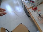
my short circuited load was like this (two thin cable which have roughly 30 cm length)
20150417_115350.jpg
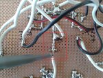
then i replaced my short circuit like this (i disabled the cables)
20150417_115057.jpg

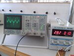
then the result:
20150417_115214.jpg

there is current that was searched by me for weeks!

the question is that: can two parallel cables were connected each other like this have large inductance(reactance) to limit current too much at 80kHz ?
 

looking at the waveform there is an inductance somewhere to limit the di/dt (all the wiring back to the supply & caps?) also still a resonant component from the way the current looks to be turning over, (C caps on rails and wiring inductance) you really need a low impedance pcb with wide tracks, double sided to remove all these extra wiring L's and better C's close to the H bridge to remove their effect also, then shorting the load will cause very large currents...!
 
I think Orson's got it. That PCB just isn't going to cut it; you need a REAL PCB, you need a ground plane.
 
  • Like
Reactions: fedaye

    fedaye

    Points: 2
    Helpful Answer Positive Rating
thanks a lot, but i do not have enough time for this certainly. i wonder only:
can you say me if i use solder tracks instead of the cables would be better?
 

Solder tracks are far from being optimal connections, tin resitivity is about the tenfold value of copper. But it's the wire length and particularly the wire loop area that creates unwanted circuit inductance and most likely dwarts the intended circuit behaviour. In this relation short solder tracks, or better straight wires soldered to the stripboard are better.
 
  • Like
Reactions: fedaye

    fedaye

    Points: 2
    Helpful Answer Positive Rating
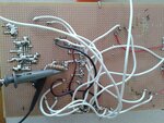
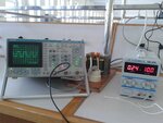
today i have connected a 10 ohm resistor instead of short circuit like this:
20150420_111224.jpg
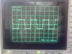
then the result:
20150420_111056.jpg
20150420_111118.jpg
i think everything is fine
according to my calculations the current must be 0.35 A for this situation (10/2=5, 5/10=0.5, 0.5/(2)^0.5=0.35 A)
there is 0.24 A, i think 0.11 A mistake is due to solder resistances+skin effect+additional inductances of the wires.
thanks a lot for your helpings guys, especially Orson.
 

Status
Not open for further replies.

Part and Inventory Search

Welcome to EDABoard.com

Sponsor

Back
Top