Continue to Site

Welcome to EDAboard.com

Welcome to our site! EDAboard.com is an international Electronics Discussion Forum focused on EDA software, circuits, schematics, books, theory, papers, asic, pld, 8051, DSP, Network, RF, Analog Design, PCB, Service Manuals... and a whole lot more! To participate you need to register. Registration is free. Click here to register now.

generating 20khz pwm from sg3525

Status
Not open for further replies.

Muhammad Ilyas Khan

Newbie level 6
Newbie level 6
Joined
Jan 20, 2015
Messages
11
Helped
0
Reputation
0
Reaction score
0
Trophy points
1
Activity points
104
hi , i am new in electronics and my smester project is designing buck converter controlled by sg3525. my sg3525 is correct for pwm generation but problem is that i want to use 20khz frequency and the circuit i designed has minimum frequency of 400khz . so question is that is how to generate 20khz from sg3525 by the circuit given below. Capture.PNG
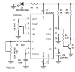
please help me this is my project to submit.
thanks
 

**broken link removed**

This article may help you
 

thank you very much of all for helping me..and i am very glade for helping me, fvm. but sir i have connected potentiometer with pin 6 of 1kohm , when i set the value of potentiometer to minimum (mean zero) then frequency is 400khz and by increasing the value of potentiometer the frequency increases more ,which is not my required frequency , my required frequency is 20khz .so please suggest me the circuit for 20khz to generate. i have uploaded the circuit diagram i am using . if any error is there in my circuit please tell me about that . thankssssss.....
 

The circuit diagram is correct, and the 100k frequency adjustment potentiometer should be able to get you well below 20 Khz.

Check the valueless of the components and correct connections around pins 6 and 7.
Something is not quite right in that part of the circuit.
 
If you are still having problems upload the data sheet for the part and revision you are using. There are many mfg and rev's of this part, i do not know if all parts use the exact same timing graph.

And my guess is that it is your 100K pot giving you trouble. Use a single resistor, or two if you have to. According to the data sheet i looked at the answer is 7K ohms total.
 
thank u very much of all of your replies...actualy acording to formula 1/Cf(0.7Rt+3Rd) i recalculated the values and i put the value for Cf =0.1nf and Rd=0 in the circuit and by calculating the value of Rt for 20khz was 0.714Mohm . and i was using mistakenly :-( 1k ohm. now i am strongly sure :wink: that by using 1Mohm it will work.
again i thanks alot of you for replies....
 

Status
Not open for further replies.

Similar threads

Part and Inventory Search

Welcome to EDABoard.com

Sponsor

Back
Top