Continue to Site

Welcome to EDAboard.com

Welcome to our site! EDAboard.com is an international Electronics Discussion Forum focused on EDA software, circuits, schematics, books, theory, papers, asic, pld, 8051, DSP, Network, RF, Analog Design, PCB, Service Manuals... and a whole lot more! To participate you need to register. Registration is free. Click here to register now.

frequency meter resolve to 0,01Hz

Status
Not open for further replies.
Hi all,

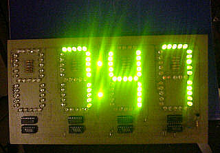
Now I want to display the freq with very large 7 segment display (20cm height, combine from single leds, 20 leds per segment). Can I use the scan technic or will I need any driver?

Thanks!
 

this kind of display is usually driven with row multiplexing

row1
row2
row3
...
last row
row1

there is also an alternative to use column multiplexing but because there are much more columns the refresh rate needs to be higher and the leds may be dimmed or flicker.
The scan technique is different because you have to further break each character to be shown in led lines.
The current needed depends on the display but in any case you need an external device (like a transistor) to provide the high current.

Alex
 
  • Like
Reactions: All4U

    V

    Points: 2
    Helpful Answer Positive Rating

    All4U

    Points: 2
    Helpful Answer Positive Rating
Dear Alex,

As I said, I intend to combine single leds to make big 7segment (20leds/segment, then about 20x7x4=560 single leds in total, some addition leds for decimal point...).
Other word, how to display with 4 set of 7 segment which required high current?

Thank in front.
 
Last edited:

I'm not sure what you are asking ask, the way to multiplex the leds is like described in my previous post, obviously you will need external devices to control the high current , like a ULN chip or transistors.

Alex
 

**broken link removed**
77_1314125261.jpg
 

Thank you for your reply,

I see SPI combined led some where (sites) before but I have not try it due to my poor ex on SPI...

I built an actual board as per your suggest...using transistors and uln2803....

But when displaying the frequency....it appeared some "strange" digits (such as "-", "|_", etc...)...(look again, it appear in proteus simulation also)...so i think the program may not well...
 

The logic high at the input of ULN2803 makes the output active low, ie it inverts. If software sets active lo to lit, now it is turning it off. For example if 0 is to be displayed now "-" center g segment is lit. If this is the case invert outputs in software or use an external inverter ic like cd4069 between mcu and ULN2803.
 
Last edited:

The logic high at the input of ULN2803 makes the output active low, ie it inverts. If software sets active lo to lit, now it is turning it off. For example if 0 is to be displayed now "-" center g segment is lit. If this is the case invert outputs in software or use an externa inverter ic like cd4069 between mcu and ULN2803.

No this is not the case, ULN2003 sink current when the input becomes 1 and it is connected in the cathodes of the display so there in no inverting involved, it just grounds the cathode side and the leds turn on.

Alex
 

The logic high at the input of ULN2803 makes the output active low, ie it inverts. If software sets active lo to lit, now it is turning it off. For example if 0 is to be displayed now "-" center g segment is lit. If this is the case invert outputs in software or use an externa inverter ic like cd4069 between mcu and ULN2803.

I understand what you refer...but the logic for uln surely not the cause and I have tried to display some number such as 1234 as good (I can do this test by assigned F=1234 in the program)....the bad display when I applied the freq from the zero crossing...Do you think the data type may cause this problem...?
 
Last edited:

So main part of displaying from digit registers is ok.This could happen if resetting the display routines wihout leting it to complete. Once rgister is updated stop taking samples and disply. See post #13. Accuracy of calculations, you have to deal afterwords. Can you show the code.
 
Last edited:

You should also consider some analog input circuitry. The 220 mains can be really dangerous to both your life and your cuircuit's life. If i was to do it, then i'd probably put the mains voltage through a transformer with some really large ratio (~150-200, because the peak voltage in mains network is 1.41x the rms value, which is the commonly used 220/230/250 VAC, and that gives a little more than 350V possible in peak). Which would give you signal in boundaries acceptable by TTL ciurcuitry. Next thing is that signal coming out of transformer will be bipolar. That means you need to rectify it with single diode or shift levels with opamp. Another thing is that you are may need a lowpass filter to reduce any HF noise.

I'd also put a series resistor and a 5V1 zener across counter input and ground should there be any mains voltage spikes, which even after transformation would exceed tolerable limits. I dunno where are u from, but in Poland where I live, the mains network isn't very reliable and such things happen.
 

No this is not the case, ULN2003 sink current when the input becomes 1 and it is connected in the cathodes of the display so there in no inverting involved, it just grounds the cathode side and the leds turn on.

Alex
Consider driving directly from mcu. logic 0 on mcu ouput will connect led to ground but in this case it is invertd. uln2003 and uln2803 both invert logic level.
 

Attachments

  • ULN2803-D.pdf
    92.3 KB · Views: 97
  • uln2003.pdf
    110.5 KB · Views: 81

I think I misunderstood what you said in the previous post, you were saying the same thing I said, that the led will turn on with 1 in the input and turn off with 0 but I miisanderstood that you have to set 0 to light the led.
Yes a common emitter output inverts the signal

Alex
 

Dear all,

The invert logic for ULN will not hurt, It can be changed easily in the program...
The code I have post in #16 this thread before....
Here is my Zero-crossing circuit...yes I put the step down isolated transformer to 15V first...
zerocrossing.JPG

Thanks!
 

Hi all,

I have used the oscilloscope for checking the zero-crossing and I think this circuit give bad signal...(although when simul in proteus is good)....Any one who have done a good zero-crossing could help me? I heard that AVR have zero-crossing inside....I only have Atmega32 in hand..and I read its datasheet without any page indicated about zero-crossing....

This urgent now...please help me
 

hi
i need help to write my project of f counter using pic16f877 and c code
what should my write on it
i wanna write 4 chapters
thanks
 

You need to be more specific about project considerations. What are the frequencies you intend to measure? And what are the amplitudes of input signals?

I don't know what are project form requirements in your case, but when i was in the uni, a project of that kind usually comprised of some introduction concerning the purpose of the circuit, analysis of existant methods of measurement with their pros and cons. Second chapter would contain contain info about your design (calculations, component selection, cost considerations etc). The third chapter would desribe the device built. I would add real photos of the device as well as some performance tests proving that this circuit works as intended. The last chapter IMO should contain you conslusions about the design. There you place an information on whether the circuit worked as intended or not, if you had any particular difficulties and so on. I this chapter you could place some conclusions about the thing that you would accomplish in other way if you were to design that circuit once more.

And I'll repeat: that's only what I would do on my uni. Yours may have completly different approach to project form.
 

have any one had a pdf for frequency meter using 16f877a
 

Status
Not open for further replies.

Similar threads

Part and Inventory Search

Welcome to EDABoard.com

Sponsor

Back
Top